High Pass Filter Calculator, Simulation, and Theory
A high-pass filter (HPF) is a circuits that allow high frequency signals to pass through while blocking lower frequencies. This can be useful in may applications like filtering out the lower bass frequencies of a music signal to a tweeter speaker (speaker designed to produce high frequencies). Additionally these filters can remove unwanted DC signals from a circuit by providing AC coupling. An example of this can be found in an oscilloscope’s AC coupling option. This is effectively a high pass filter tuned to block very low frequencies, mainly 0 Hz which is DC. Another example of this would be if you where generating a sin wave using an oscillating circuit that only produced values in the positive range but you wanted to remove the DC offset and send the AC signal, oscillating around 0, to a speaker.
RC High Pass Filter Calculator
For more information on how to use this online calculator view the documentation here
Resistor Calculator
Capacitor Calculator
Filter Design
When designing a rc filter that will actually be built with real components first select the desired cut-off frequency of the filter. Using the given frequency you then select your component values.
- First, choose from a standard value capacitors you think will produce a reasonable and usable resistor value.
- Next, you calculate the needed resistor value by using the following equation and solve for the R value (resistor value).
- Once you have the desired R and C values you then need to determine what the voltage source will be that is providing the signal to the RC filter.
- It is important that you select component values that are able to handle the input voltage and current you expect to flow through the circuit. So be sure to choose component values that are rated for your application
That is it, now all you need to do is get the filter components as close to the calculated values as you can.
The odds are slim you will be able to find the exact values for your resistor and capacitor values but if you get close enough than you should be good to go.
If you are worried the real values are too far away just plug in the values you can get into the filter calculator and see if the cutoff frequency of a high pass filter with the real component values will give the output voltage while attenuating the low frequency signals to an acceptable level for your application.
One word of caution when designing rc filters, try to avoid using an electrolytic capacitor as it is polarised and will have problems with the AC signal being fed into the circuit. Stick with standard ceramic capacitors unless your design requires something else.
That is it, just using simple series capacitors and resistors produces a high-pass or low-pass filter depending on their orientation.
Additionally, if you want a slightly different design check out lc filters. The are just like rc fliters but use an inductor and capacitor instead
RC High Pass Filter
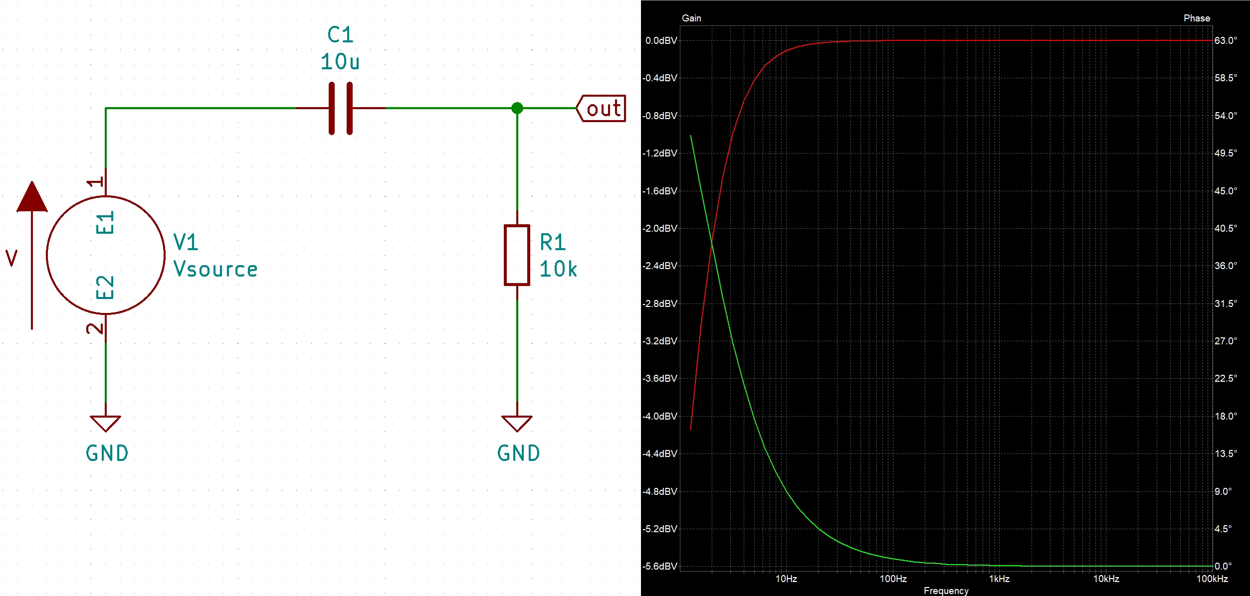
The simplest HPF circuit is the RC high pass filter. This HPF is just a capacitor in series with a resistor where the output is taken in between the two components.
The basic idea for how this filter works is at high frequencies the capacitor $C_1$ acts like an short so that the entire input signal is present on the output. Conversely, at low frequencies the capacitor $C_1$ acts like a open effectively grounding the output and therefor making the output equal zero.
Below is a video of us demonstrating how to do a KiCad simulation of an RC HPF circuit.
For a more complex design check out active filters. They require more components but allow for increased control and precision. One popular choice is a sallen-key filter. The sallen-key active filter uses high-speed op amps (or regular op amps if acceptable) instead of simple passive components (a resistor and capacitor in the case of an RC filter).
RC High Pass Filter Simulation (Video)
This is a video of a KiCad high pass filter simulation showing the effects of adjusting the resistor and capacitor in a RC high pass filter.
Theory (Approximation)
For the RC HPF approximation equation just use $X_{C_1}$ for the capacitor and treat it like a resistor. Below is the equation for a voltage divider $$V_{out} = V_{in}{R_1 \over{R_1 + X_{C_1}}}$$
$$\boxed{V_{out} = V_{in}{R_1 \over{R_1 + {1 \over(2 \pi f C_1)}}}}$$
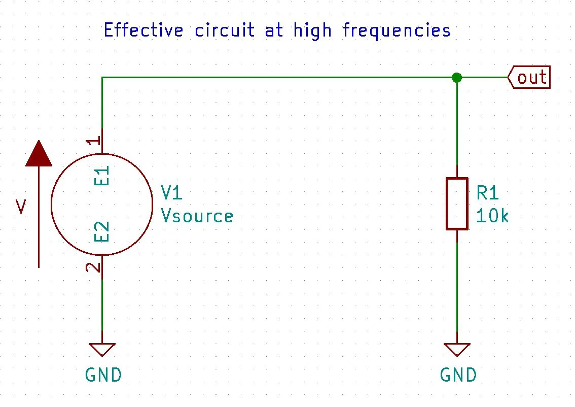
At high frequencies
Using the capacitive reactance equation we can see that as $\uparrow f \Rightarrow {1 \over(2\pi (f \uparrow) C_1)}\downarrow \Rightarrow X_{C_1} \downarrow$ and at a high enough frequency $X_{C_1} \approx 0$ when this happens the RC HPF equation turns into $V_{out} \approx V_{in}$ thus passing all high frequencies
$$V_{out} = V_{in} {R_1 \over R_1 + {1 \over(2 \pi {f} C_1)\uparrow}\downarrow}\uparrow$$
$$V_{out} \approx V_{in} {R_1 \over R_1 + 0} \approx V_{in}\cancel{R_1 \over R_1} \approx V_{in}$$
$$\boxed{V_{out} \approx V_{in}}$$
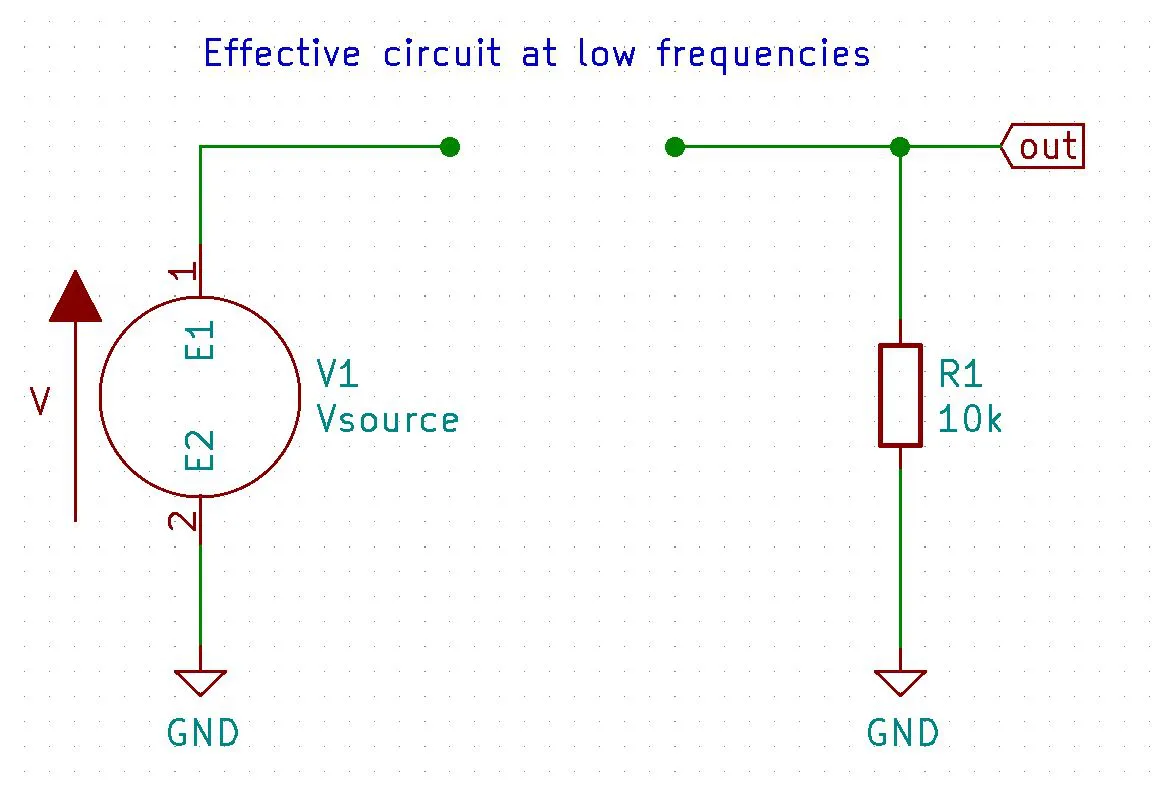
At low frequencies
Conversely, as frequency goes down $\downarrow f \Rightarrow {1 \over(2\pi (f \downarrow) C_1)}\uparrow \Rightarrow X_{C_1} \uparrow$ and at a low enough frequency $X_{C_1} \approx \infty when this happens the RC high pass filter equation turns into V_{out} \approx 0$ thus blocking all low frequencies including DC
$$V_{out} = V_{in} {R_1 \over R_1 + {1 \over(2 \pi f C_1)\downarrow}\uparrow}\downarrow$$
$$V_{out} \approx V_{in} {R_1 \over R_1 + \infty } \approx V_{in}0 \approx 0$$
$$\boxed{V_{out} \approx 0}$$
Theory (Complex solution)
The complex solution uses $X_{C_1} = {j \over {w C_1}}$ instead of $X_{C_1} = {1 \over {w C_1}}$ where $w = 2 \pi f$
$$V_{out} = V_{in}{R_1 \over{R_1 - {j \over{w C_1}}}} = V_{in}{1 \over{1 - {j \over{R_1 w C_1}}}}$$
taking the absolute value of a complex number will give us its magnitude. Meaning if we take the absolute value we will get the amplitude and not worry about the phase. Here is the calculation
$$\boxed{V_{out} = V_{in}{1 \over{(1 - {1 \over{R_1^2w^2 C_1^2}})^{1 \over {2}}}}}$$
Usages
AC Coupling
Oscilloscopes have options to remove the DC offset of a signal by turning on AC Coupling. This is just a high pass filter because the lowest frequency is 0Hz and that is DC. So a high pass filter with a very low cutoff frequency can be used to remove the DC component thus providing AC coupling.
DC Blocking
Another way you can look at this is that capacitors block DC and allow AC to travel across them. The higher the frequency the less reactance (think resistance to AC) the capacitor provides.
As the frequency goes up the reactance of the capacitor goes down. This means low frequencies will experience heavy reactance where as higher frequencies will see little to no reactance
$$\downarrow X_{C_1} = {1 \over(2\pi (f \uparrow) C_1)}\downarrow$$