Part 4 – Programming the Arduino
1: Intro
2: Power
3: Signaling
4: Program
5: Sound The Alarm
Abstract
We need to convert the PWM signals coming in from the FS-iA6B receiver into the correct signals to drive the motors of the rover 5. To do that we will us an Arduino’s digital inputs to read the FS-iA6B receivers output. Next, we will determine which direction the stick on the transmitter is pointing. Finally, we will use the joy stick’s direction to send the corresponding motor controller signals to perform the maneuver requested.
Inputs and Outputs
In our previous post we discussed the different signals that our system would use. If you have not read that yet check it out to know more about why we will select the input and output parameters that follow.
Here is a mapping between inputs and outputs for the Arduino
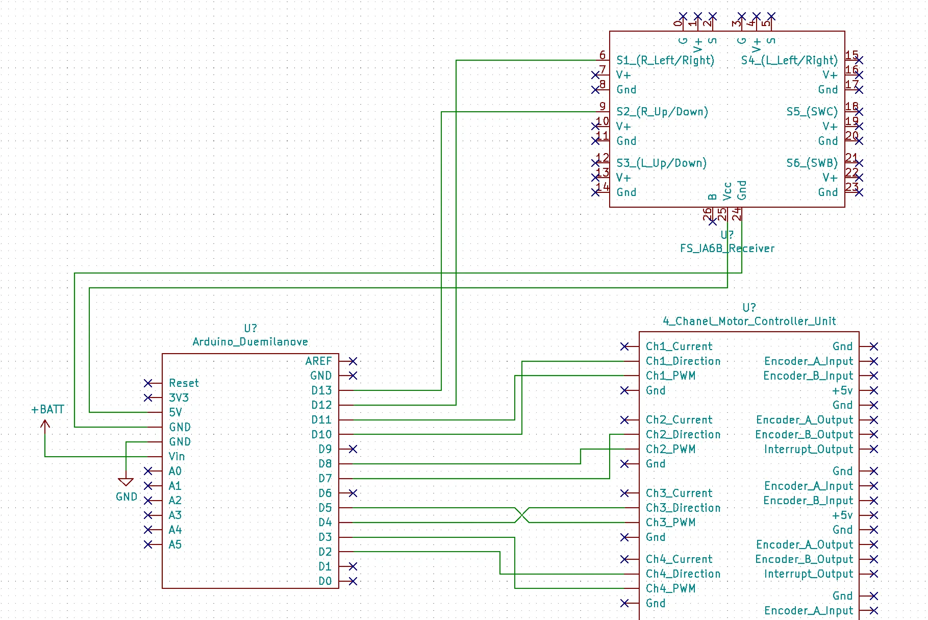
Here is the wiring diagram of how the Arduino is connected to the FS-iA6B receiver and the Motor Controller
Reading from the receiver
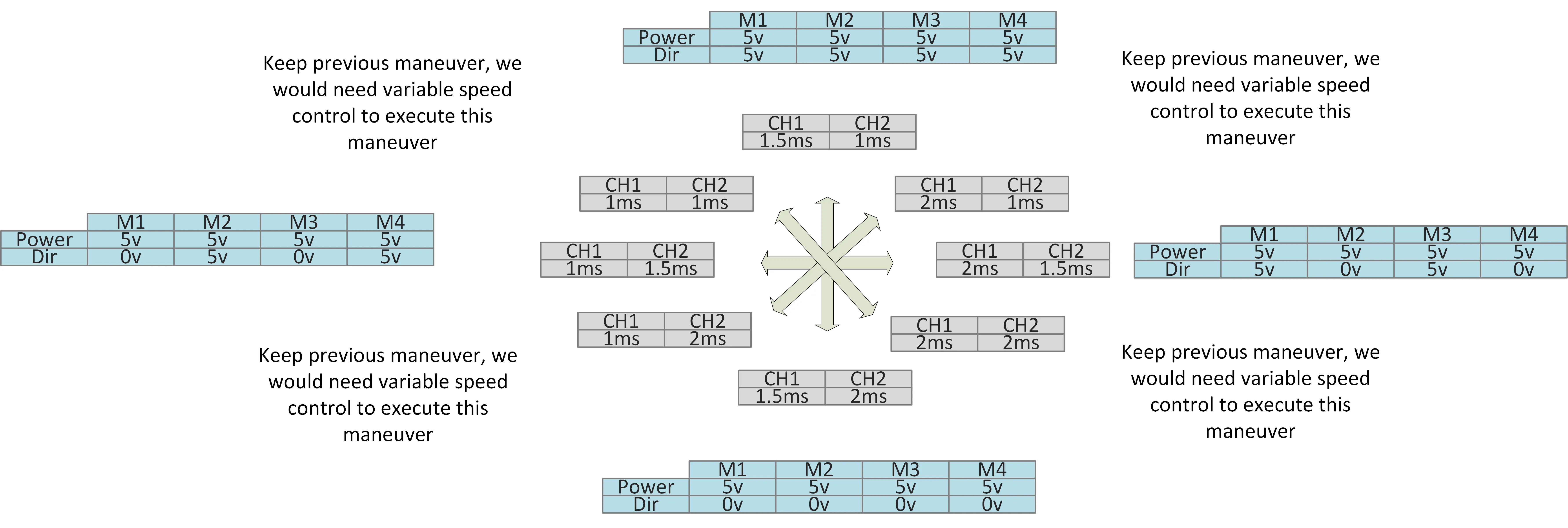
We know from the previous post that the FS-iA6B receiver is outputting a PWM signal at 50Hz and the PWM pulses have basically three positions, 1ms, 1.5ms, and 2ms. Therefore, we need to write some code to read these inputs and classify the input as one of these three positions. Additionally, we need to specify a timeout if a PWM pulse has not come in so that the reading of the pin will hang (reading a pin via pulseIn() is a blocking operation.
//Want to have a timeout that is twice as long as any one cycle should be.
//(1/50)*2/10^-6 = 40000. Then added a fudge factor of 10,000 to bring it to 50,000
//(1/50) = Hz to seconds
// *2 = Twice the cycle
// /10^-6 = seconds to microseconds
const int PWM_TIMEOUT_MS = 50000;

//A short pulse has a width of 1ms = 1000us
//A nutral pulse has a width of 1.5ms = 1500us
//A long pulse has a widht of 2ms = 2000us

//Up is a short pulse
const int UP_THRESHOLD = 1250;
//Down is a long pulse
const int DOWN_THRESHOLD = 1750;

//Left is a short pulse
const int LEFT_THRESHOLD = 1250;
//Right is a long pulse
const int RIGHT_THRESHOLD = 1750;

const int LEFT_RIGHT_PIN = 12;
const int UP_DOWN_PIN = 13;

const int CH1_PWM_PIN = 11;
const int CH1_DIR_PIN = 10;
const int CH2_PWM_PIN = 8;
const int CH2_DIR_PIN = 7;
const int CH3_PWM_PIN = 5;
const int CH3_DIR_PIN = 4;
const int CH4_PWM_PIN = 3;
const int CH4_DIR_PIN = 2;

typedef struct {
  int up;
  int down;
  int left;
  int right;
} Controls;

Controls NewControls(){
  Controls con = {0, 0, 0, 0};
  return con;
}

void setup() {
  //Recever pins
  pinMode(LEFT_RIGHT_PIN, INPUT); // Ch 1 of recever
  pinMode(UP_DOWN_PIN, INPUT); // Ch 2 of recever

  //Motor controller pins
  pinMode(CH1_PWM_PIN, OUTPUT);
  pinMode(CH1_DIR_PIN, OUTPUT);
  pinMode(CH2_PWM_PIN, OUTPUT);
  pinMode(CH2_DIR_PIN, OUTPUT);
  pinMode(CH3_PWM_PIN, OUTPUT);
  pinMode(CH3_DIR_PIN, OUTPUT);
  pinMode(CH4_PWM_PIN, OUTPUT);
  pinMode(CH4_DIR_PIN, OUTPUT);
  Serial.begin(9600);
}
Next, we create the main loop that will read from the input pins via readControls(). This will output a structure show in the following truth table.
| up | down | left | right | |
| forward | 1 | |||
| forward right | 1 | 1 | ||
| right | 1 | |||
| back right | 1 | 1 | ||
| back | 1 | |||
| back left | 1 | 1 | ||
| left | 1 | |||
| forward left | 1 | 1 |
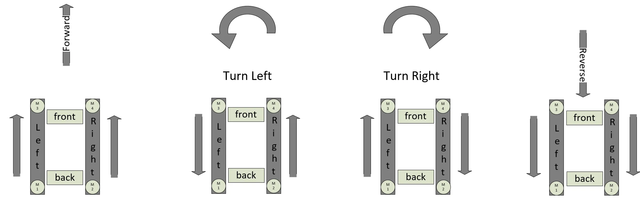
Finally, we will use the truth table to classify the direction and send the output to activate the motors and spin the treads!
void loop() {
  Controls con = readControls();

  //Neutral
  if (con.up == 0 && con.down == 0 && con.left == 0 && con.right == 0) {
    Serial.println("Neutral");
    leftTreadsOff();
    rightTreadsOff();
  }
  //Forward
  else if (con.up == 1 && con.down == 0 && con.left == 0 && con.right == 0) {
    Serial.println("Forward!");
    leftTreadsForward();
    leftTreadsFullSpeed();

    rightTreadsForward();
    rightTreadsFullSpeed();
  }
  //Forward Right
  else if (con.up == 1 && con.down == 0 && con.left == 0 && con.right == 1) {
    Serial.println("Forward Right!");
  }
  //Right
  else if (con.up == 0 && con.down == 0 && con.left == 0 && con.right == 1) {
    Serial.println("Right!");

    leftTreadsForward();
    leftTreadsFullSpeed();

    rightTreadsReverse();
    rightTreadsFullSpeed();
  }
  //Back Right
  else if (con.up == 0 && con.down == 1 && con.left == 0 && con.right == 1) {
    Serial.println("Back Right!");
  }
  //Back
  else if (con.up == 0 && con.down == 1 && con.left == 0 && con.right == 0) {
    Serial.println("Back!");

    leftTreadsReverse();
    leftTreadsFullSpeed();

    rightTreadsReverse();
    rightTreadsFullSpeed();
  }
  //Back Left
  else if (con.up == 0 && con.down == 1 && con.left == 1 && con.right == 0) {
    Serial.println("Back Left!");
  }
  //Left
  else if (con.up == 0 && con.down == 0 && con.left == 1 && con.right == 0) {
    Serial.println("Left!");

    leftTreadsReverse();
    leftTreadsFullSpeed();

    rightTreadsForward();
    rightTreadsFullSpeed();
  }
  //Forward Left
  else if (con.up == 1 && con.down == 0 && con.left == 1 && con.right == 0) {
    Serial.println("Forward Left!");
  }
  //Invalid combo
  else {
    sprintf(charBuffer, "Error combo not possible, up:%i\tdown:%i\tleft:%i\tright:%i", con.up, con.down, con.left, con.right);
    Serial.println(charBuffer);
  }


  delay(100);
}

Controls readControls(){
  Controls con = NewControls();

  //This will block while trying to sample a pulse
  leftRightChan = pulseIn(LEFT_RIGHT_PIN, HIGH, PWM_TIMEOUT_MS);
  //This will block while trying to sample a pulse
  upDownChan = pulseIn(UP_DOWN_PIN, HIGH, PWM_TIMEOUT_MS);

  if (upDownChan == 0){
    con = killUpDown(con);
  }
  else if (upDownChan < UP_THRESHOLD){
   con =  setUp(con);
  }
  else if ( upDownChan >= UP_THRESHOLD && upDownChan <= DOWN_THRESHOLD){
    con = killUpDown(con);
  }
  else if (upDownChan > DOWN_THRESHOLD) {
    con = setDown(con);
  }
  else {
    con = killUpDown(con);
  }

  if (leftRightChan == 0){
    con = killLeftRight(con);
  }
  else if (leftRightChan < LEFT_THRESHOLD){
    con = setLeft(con);
  }
  else if (leftRightChan >= LEFT_THRESHOLD && leftRightChan <= RIGHT_THRESHOLD){
    con = killLeftRight(con);
  }
  else if (leftRightChan > RIGHT_THRESHOLD) {
    con = setRight(con);
  }
  else {
    con = killLeftRight(con);
  }

  return con;
}

Controls setUp(Controls con){
  con.up = 1;
  con.down = 0;

  return con;
}

Controls setDown(Controls con){
  con.up = 0;
  con.down = 1;

  return con;
}

Controls killUpDown(Controls con){
  con.up = 0;
  con.down = 0;

  return con;
}

Controls setLeft(Controls con){
  con.left = 1;
  con.right = 0;

  return con;
}

Controls setRight(Controls con){
  con.left = 0;
  con.right = 1;

  return con;
}

Controls killLeftRight(Controls con){
  con.left = 0;
  con.right = 0;

  return con;
}

void leftTreadsForward(void){
  digitalWrite(CH2_DIR_PIN, LOW);
  digitalWrite(CH4_DIR_PIN, HIGH);
}

void leftTreadsReverse(void){
  digitalWrite(CH2_DIR_PIN, HIGH);
  digitalWrite(CH4_DIR_PIN, LOW);
}

void leftTreadsFullSpeed(void){
  digitalWrite(CH2_PWM_PIN, HIGH);
  digitalWrite(CH4_PWM_PIN, HIGH);
}

void leftTreadsOff(void){
  digitalWrite(CH2_PWM_PIN, LOW);
  digitalWrite(CH4_PWM_PIN, LOW);
}

void rightTreadsForward(void){
  digitalWrite(CH1_DIR_PIN, LOW);
  digitalWrite(CH3_DIR_PIN, HIGH);
}

void rightTreadsReverse(void){
  digitalWrite(CH1_DIR_PIN, HIGH);
  digitalWrite(CH3_DIR_PIN, LOW);
}

void rightTreadsFullSpeed(void){
  digitalWrite(CH1_PWM_PIN, HIGH);
  digitalWrite(CH3_PWM_PIN, HIGH);
}

void rightTreadsOff(void){
  digitalWrite(CH1_PWM_PIN, LOW);
  digitalWrite(CH3_PWM_PIN, LOW);
}
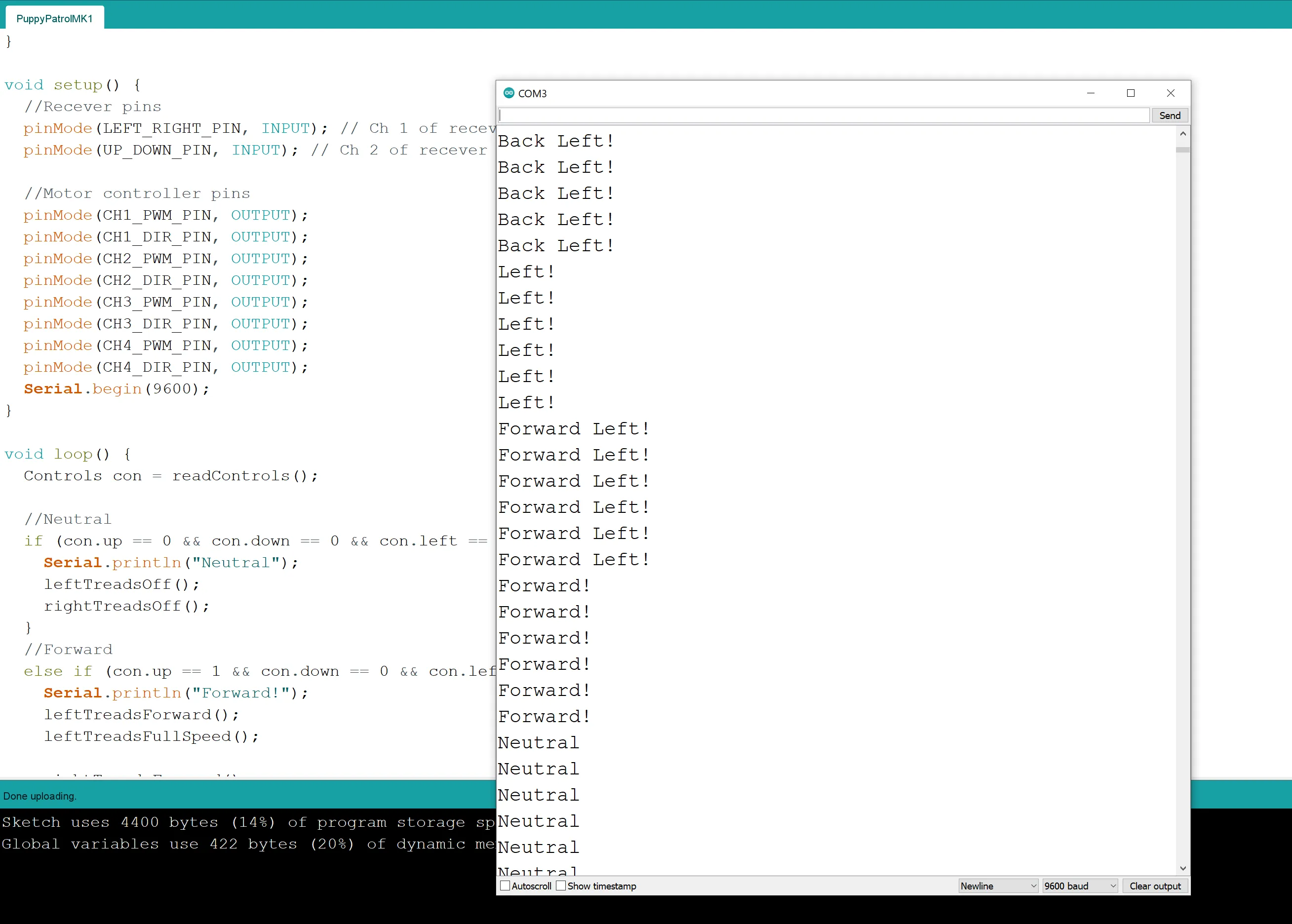
Here is what the Arduino will output via its serial console
Here is a link to our gitlab repo that has a full copy of the code
Previous: Part 3 - Signals and Controls
Next: Puppy Patrol MK1: Part 5 – The Final Step…SOUND THE ALARM!