Part 3 – Signals and Controls
1: Intro
2: Power
3: Signaling
4: Program
5: Sound The Alarm
Abstract
This section will discuss the signals from the FS-iA6B receiver to the Arduino that indicate the FS-i6X transmitter’s right stick position. Additionally, this section covers the signals from the Arduino to the motor controller that direct the speed and direction of the tanks four wheels.
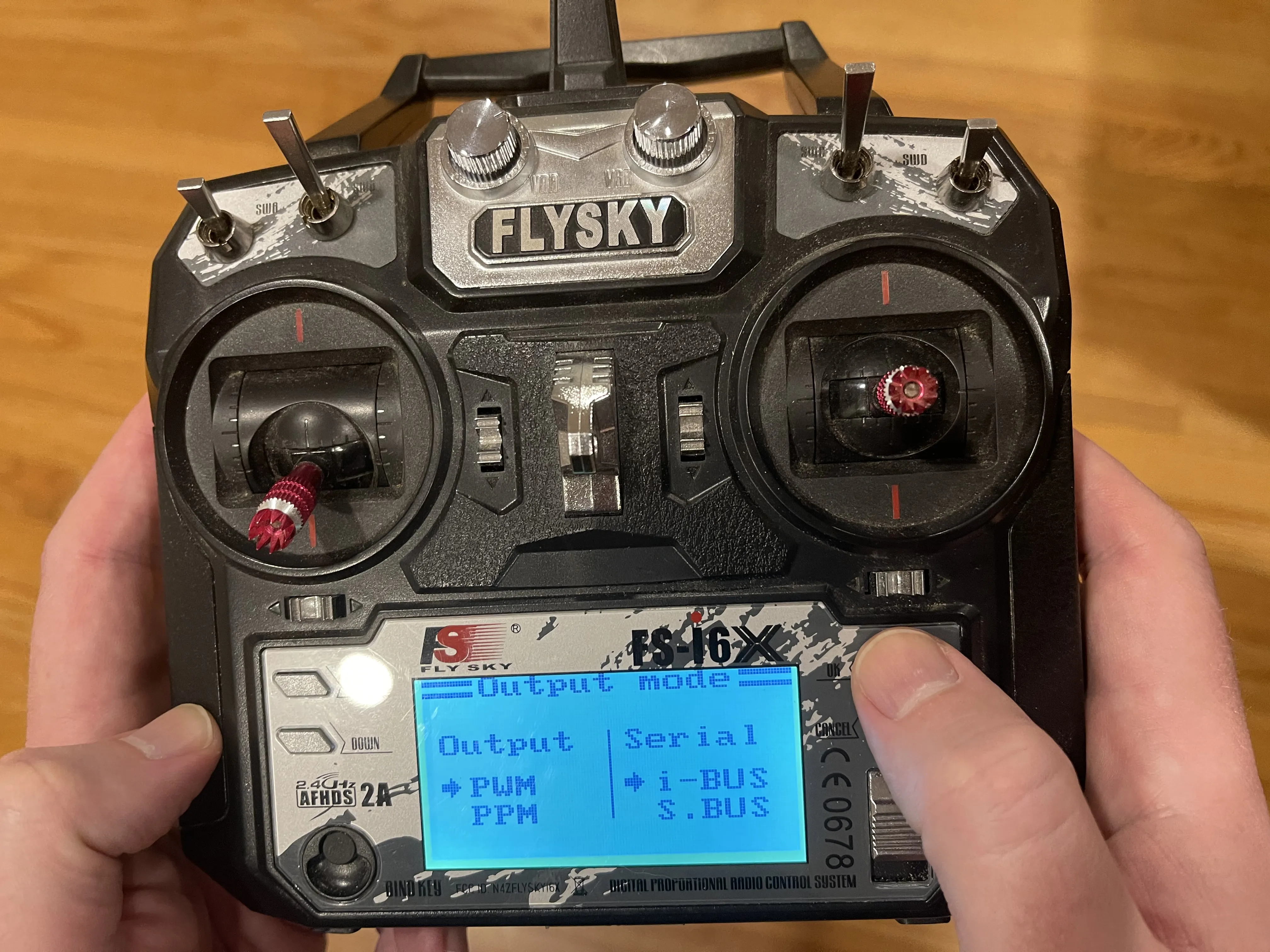
Setup FS-i6X transmitter to use PWM
Set controller to PWM (pulse width modulation) instead of PPM (pulse position modulation).
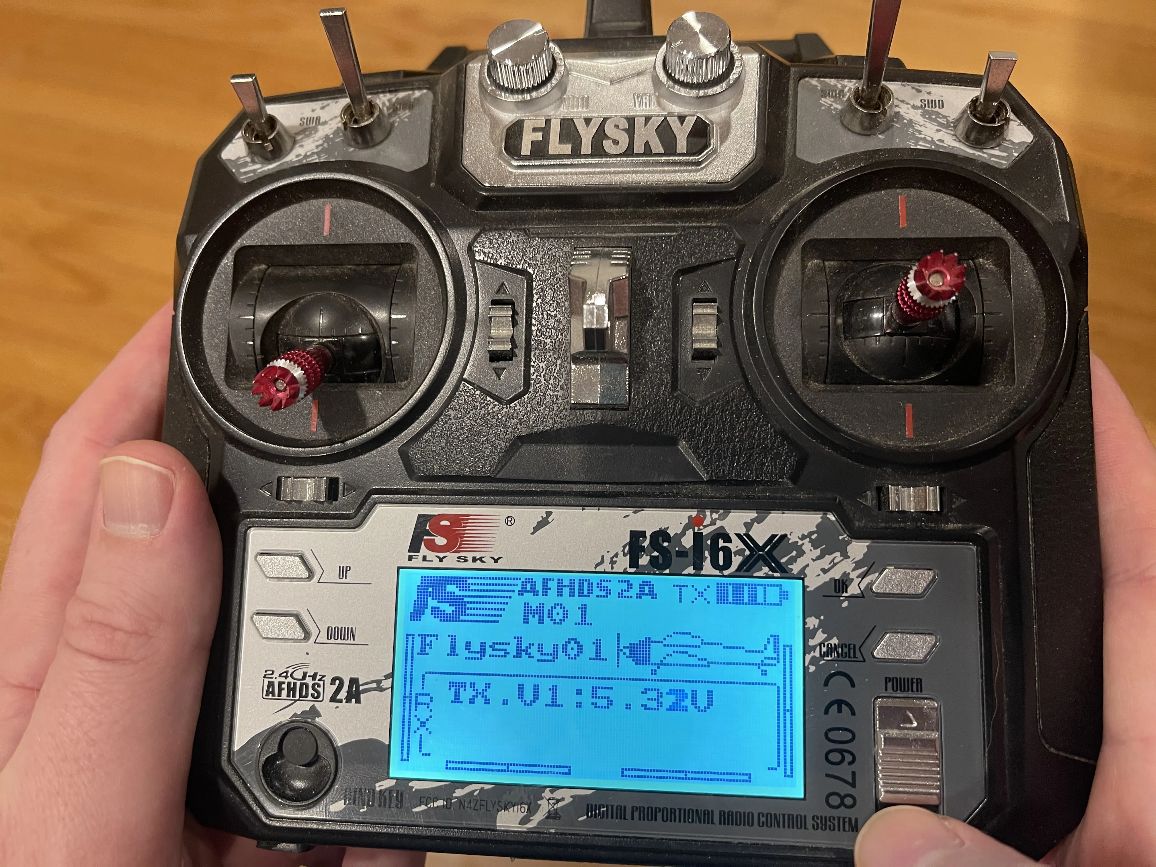
- Power on the transmitter
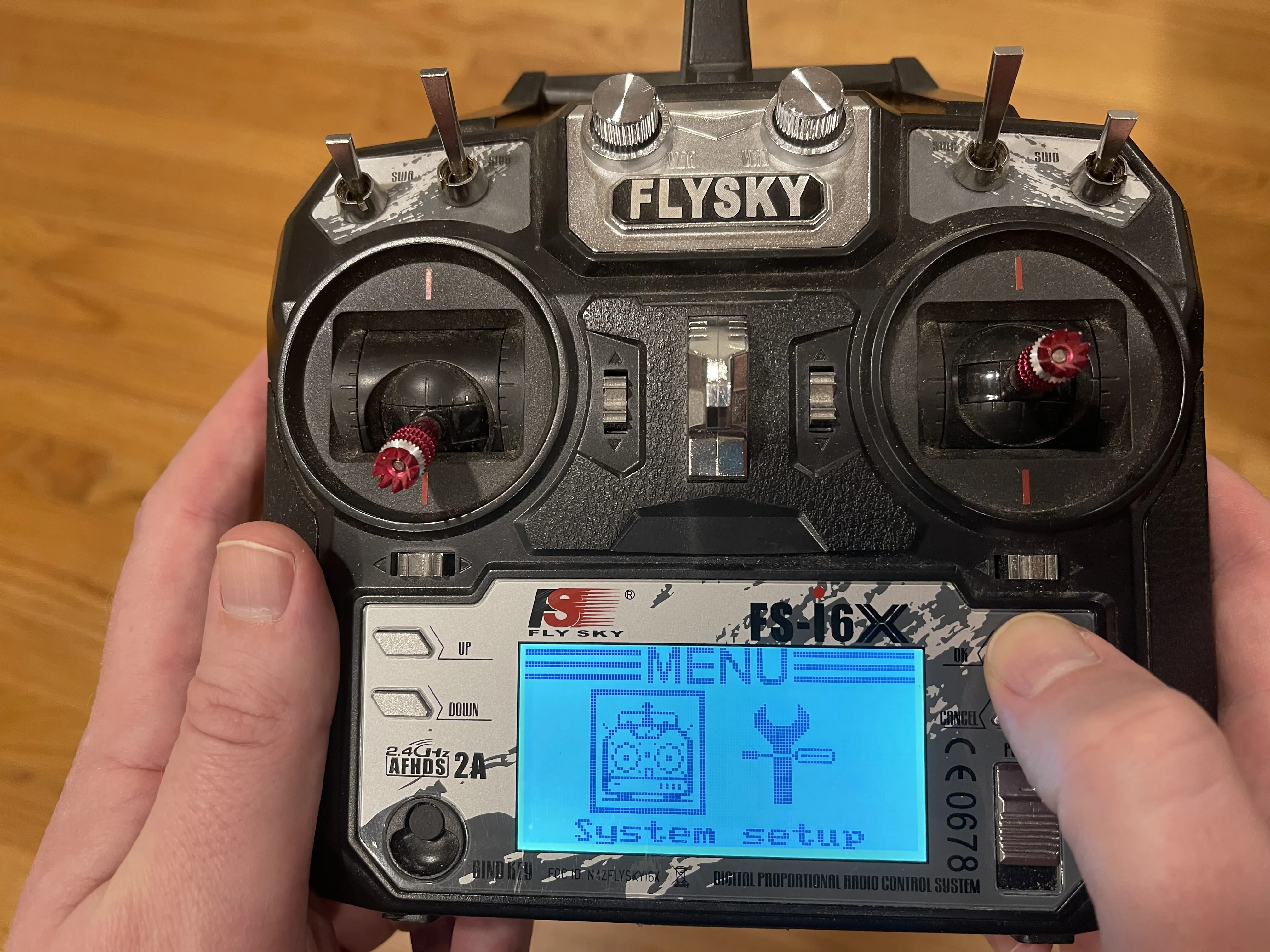
- Hold OK to see the menu then select setup
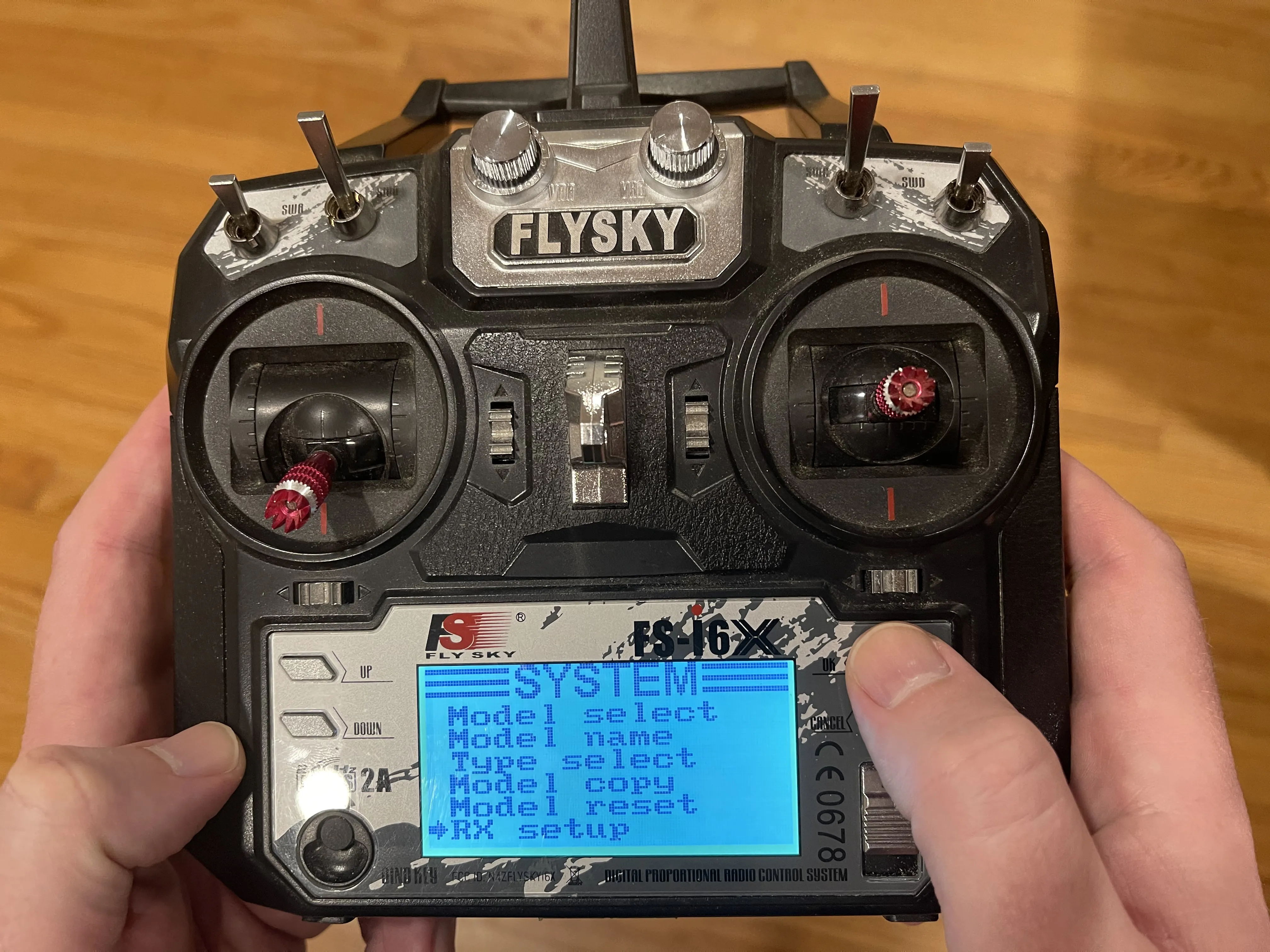
- Scroll down and select RX setup
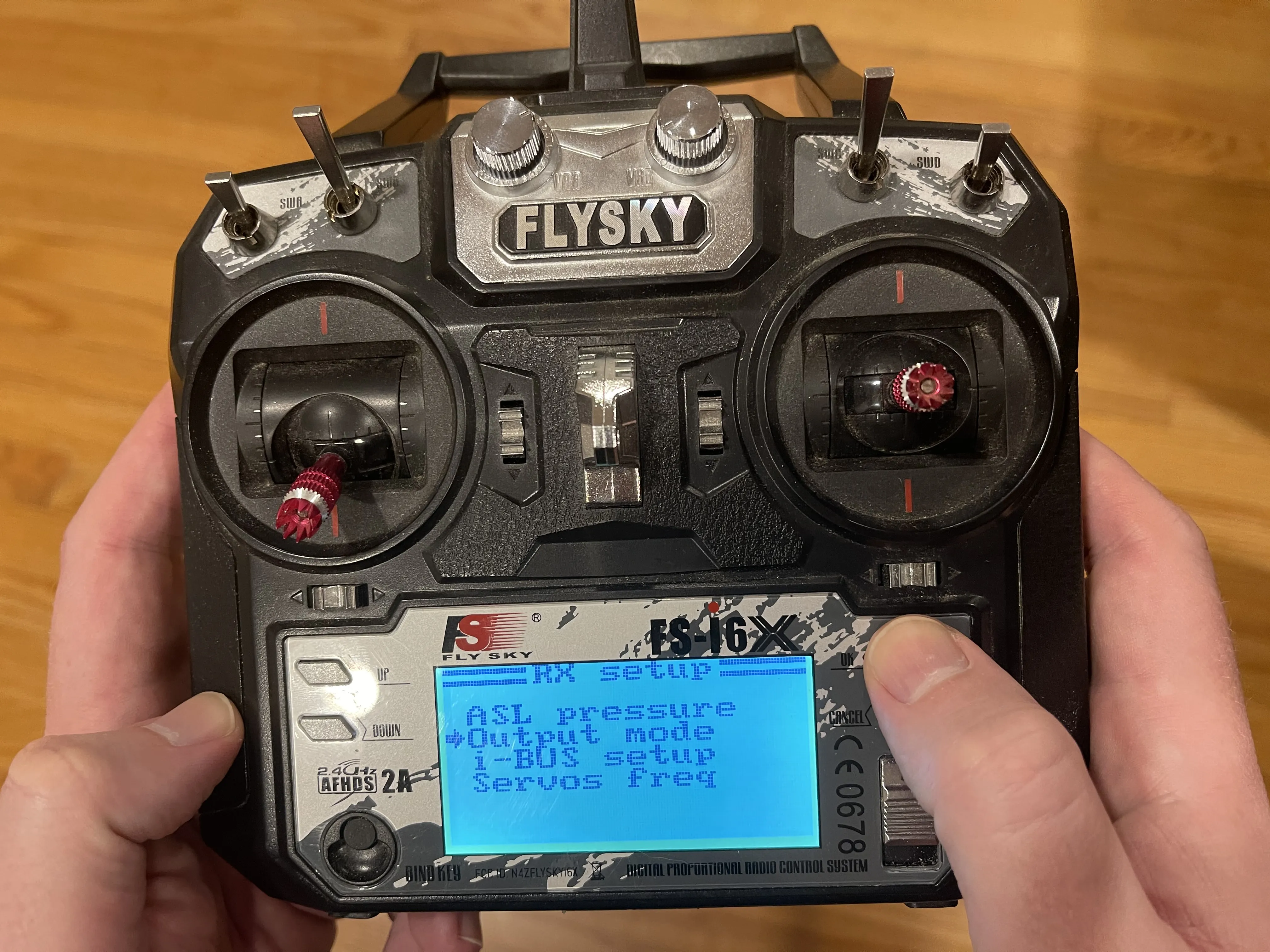
- Select Output mode
- Configure Output = PWM and Serial = i-BUS
- Press and hold cancel to confirm changes
The signal from the FS-iA6B receiver to the Arduino
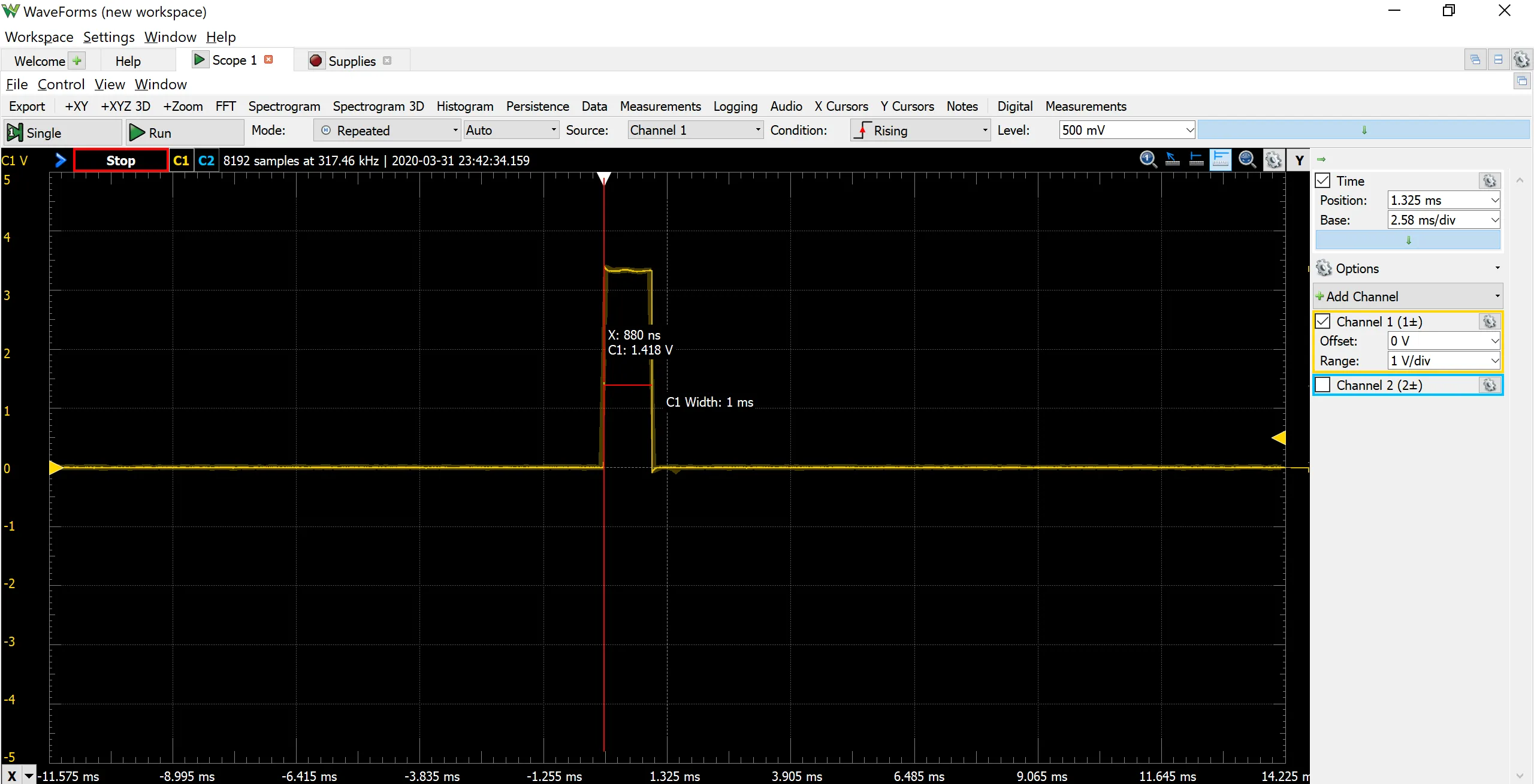
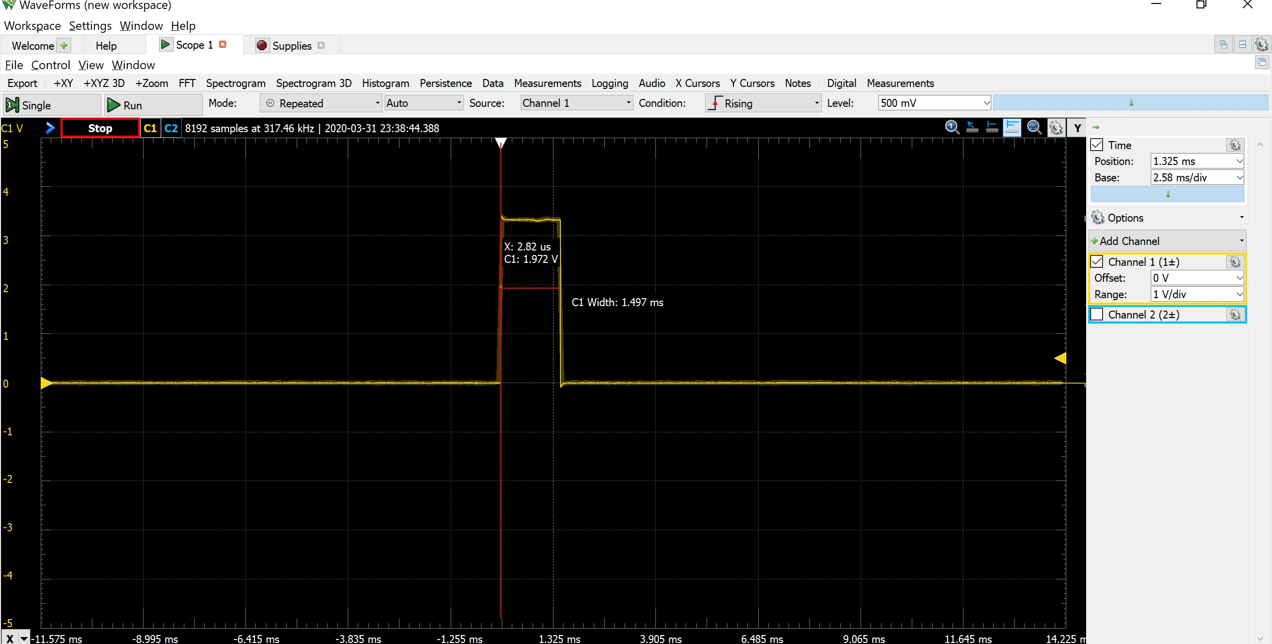
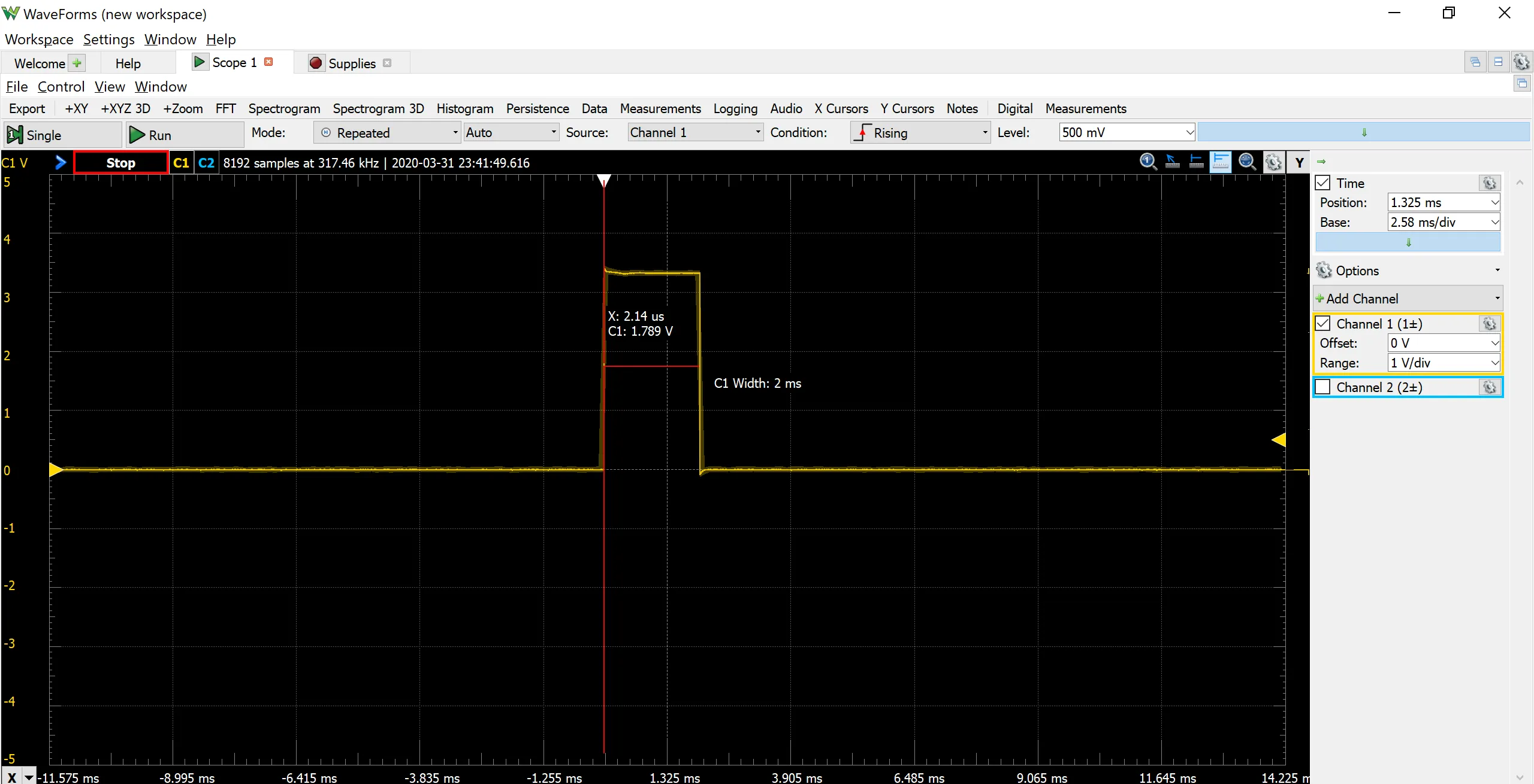
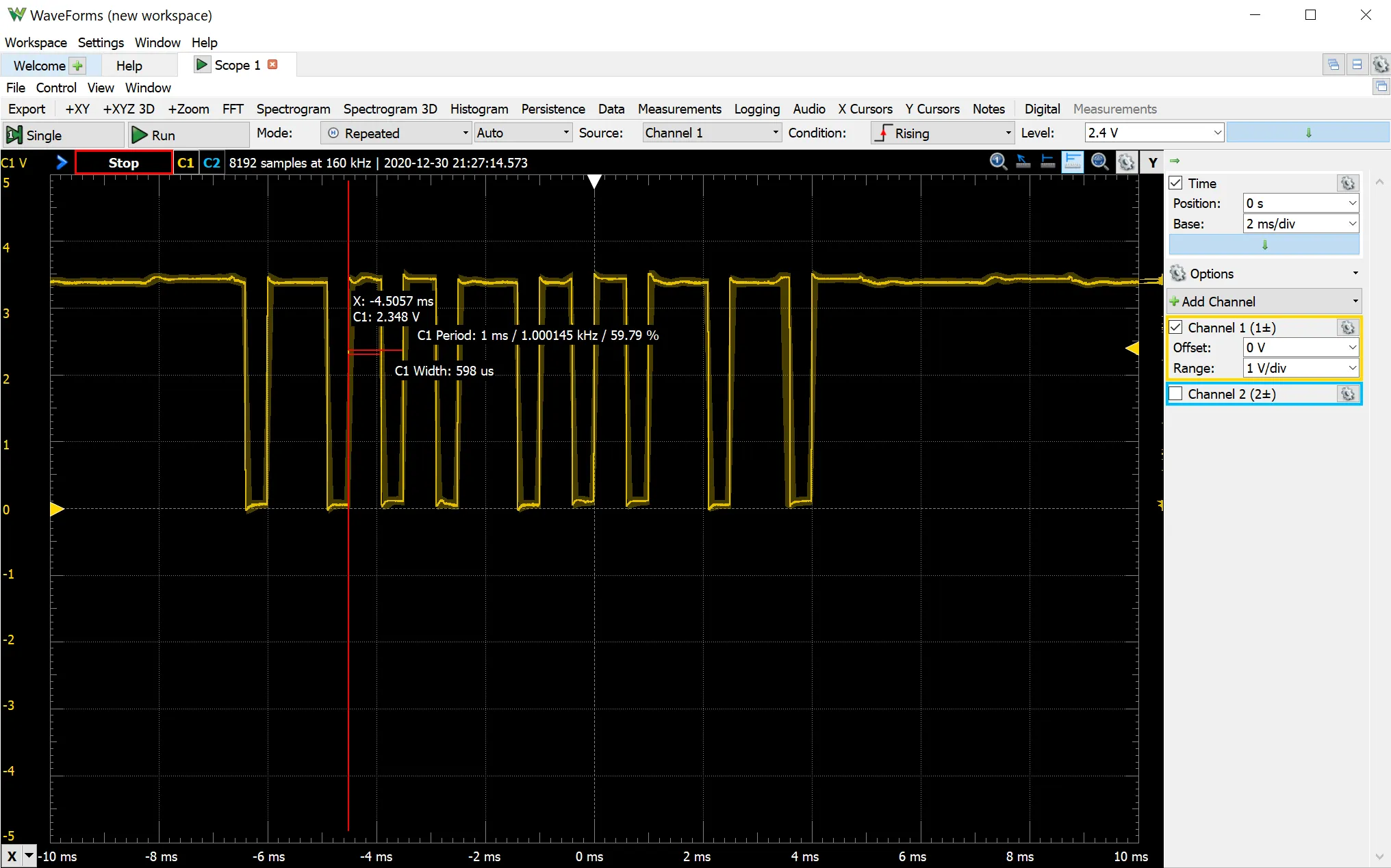
With PWM each pin outputs one channel from the transmitter. For example up/down is one channel and left/right is a different channel. In contrast, all 6 channels that the FS-i6X outputs is sent on one pin using PPM. Here are some images to illustrate the differences
PWM CH1
PWM CH2
Up
Neutral
Down
PPM CH1
Neutral
Left

Right

Up
Down
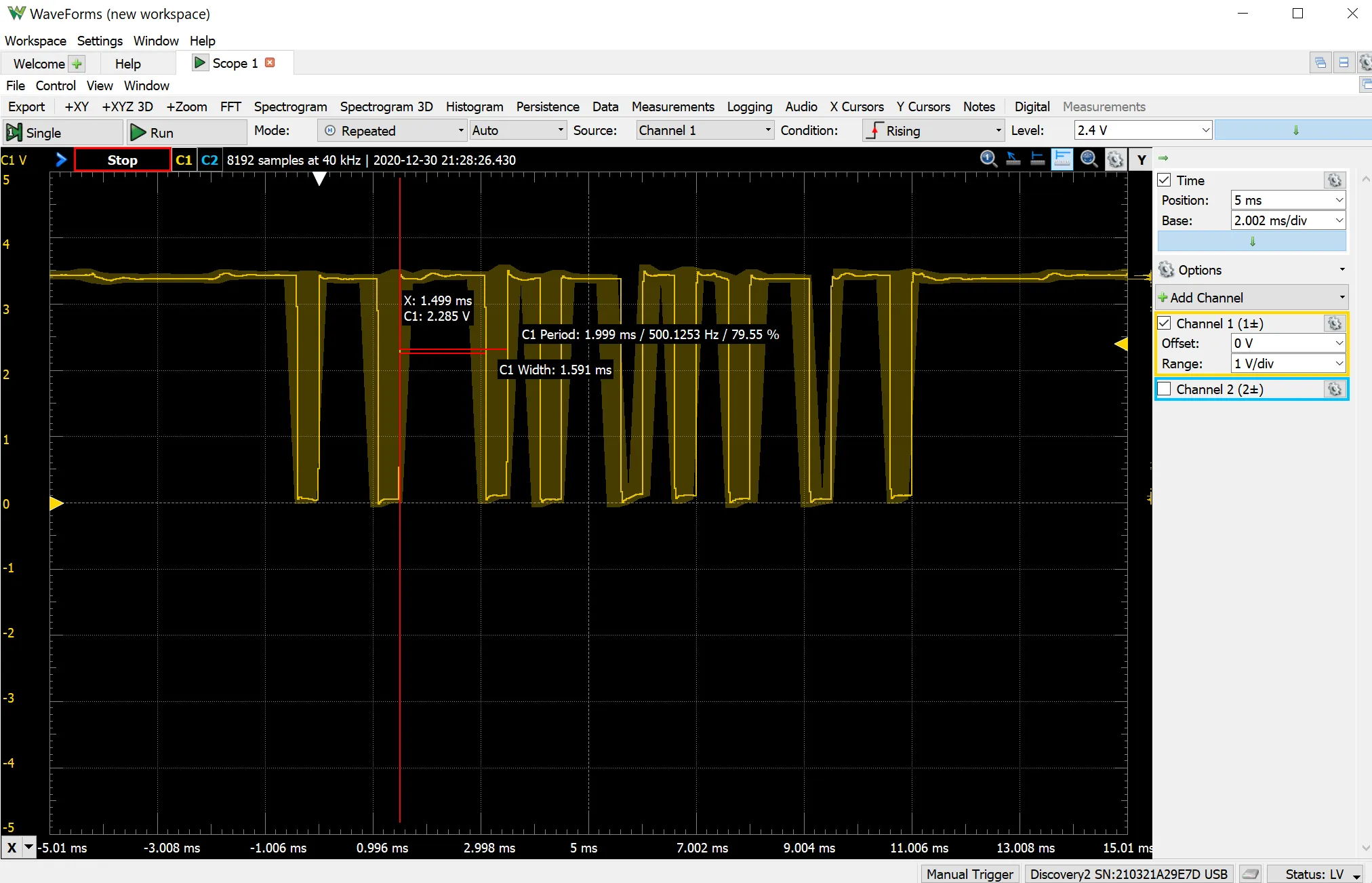
The six channels on the FS-i6X
This can be configured in the settings of the FS-i6X transmitter but here are what they are set to for this project.
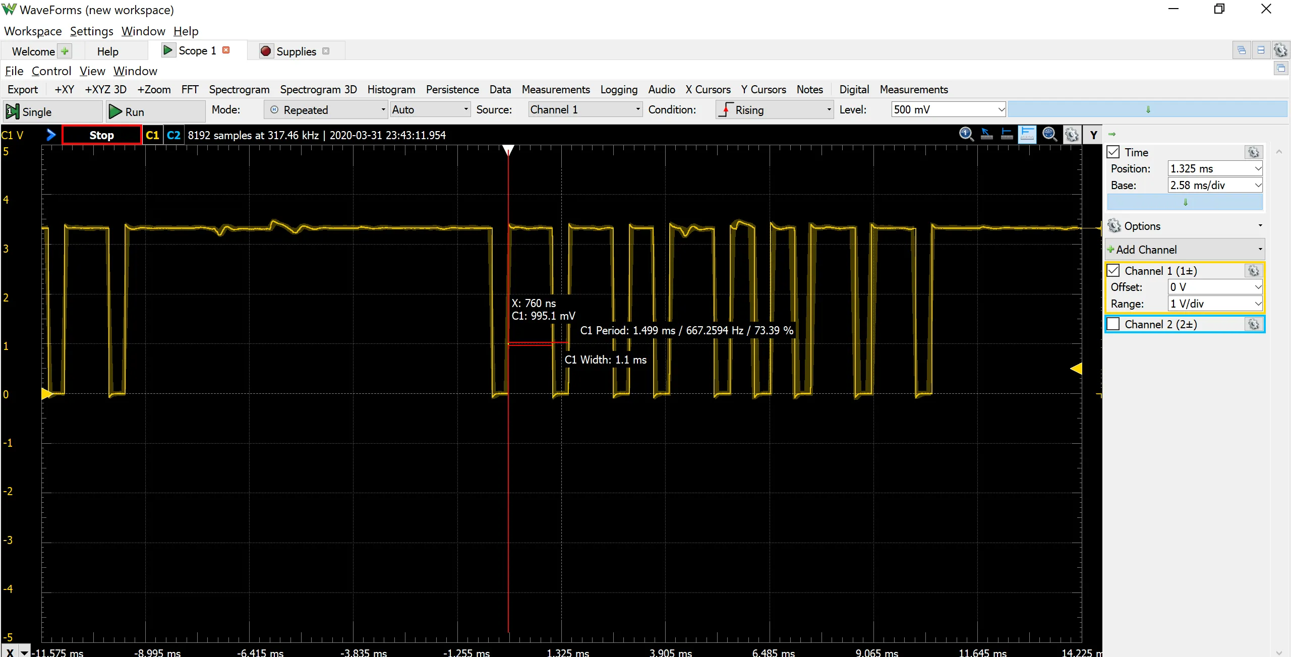
Both signals have a 50Hz frequency
| Chanel | Direction | PWM Width | PPM Width |
| ch1 (right joystick left/right) | left | 1ms | .6ms |
| neutral | 1.5ms | 1ms | |
| right | 2ms | 1.6ms | |
| ch2 (right joystick up/down) | up | 1ms | .6ms |
| neutral | 1.5ms | 1ms | |
| down | 2ms | 1.6ms | |
| ch3 (left joystick up/down) | down | 1ms | .6ms |
| up | 2ms | 1.6ms | |
| ch4 (left joystick left/right) | left | 1ms | .6ms |
| neutral | 1.5ms | 1ms | |
| right | 2ms | 1.6ms | |
| ch5 (Switch C) | forward | 1ms | .6ms |
| middle | 1.5ms | 1ms | |
| back | 2ms | 1.6ms | |
| ch6 (Switch B) | forward | 1ms | .6ms |
| back | 2ms | 1.6ms | |
| Switch A not set to a channel | |||
| Switch D not set to a channel |
Because we only need two channels (right joystick up/down and left/right) we will use PWM as it will be easier to code.
The signal from the Arduino to the Motor Controller
The Arduino is hooked up the the receiver and is receiving signals indicating the position of the right joystick on the transmitter. With this we will need to code the Arduino to produce an output that will drive the motor controller. In this section we are going to look at the signal that needs to be produced by the Arduino.
The device the Arduino is driving is this motor controller.
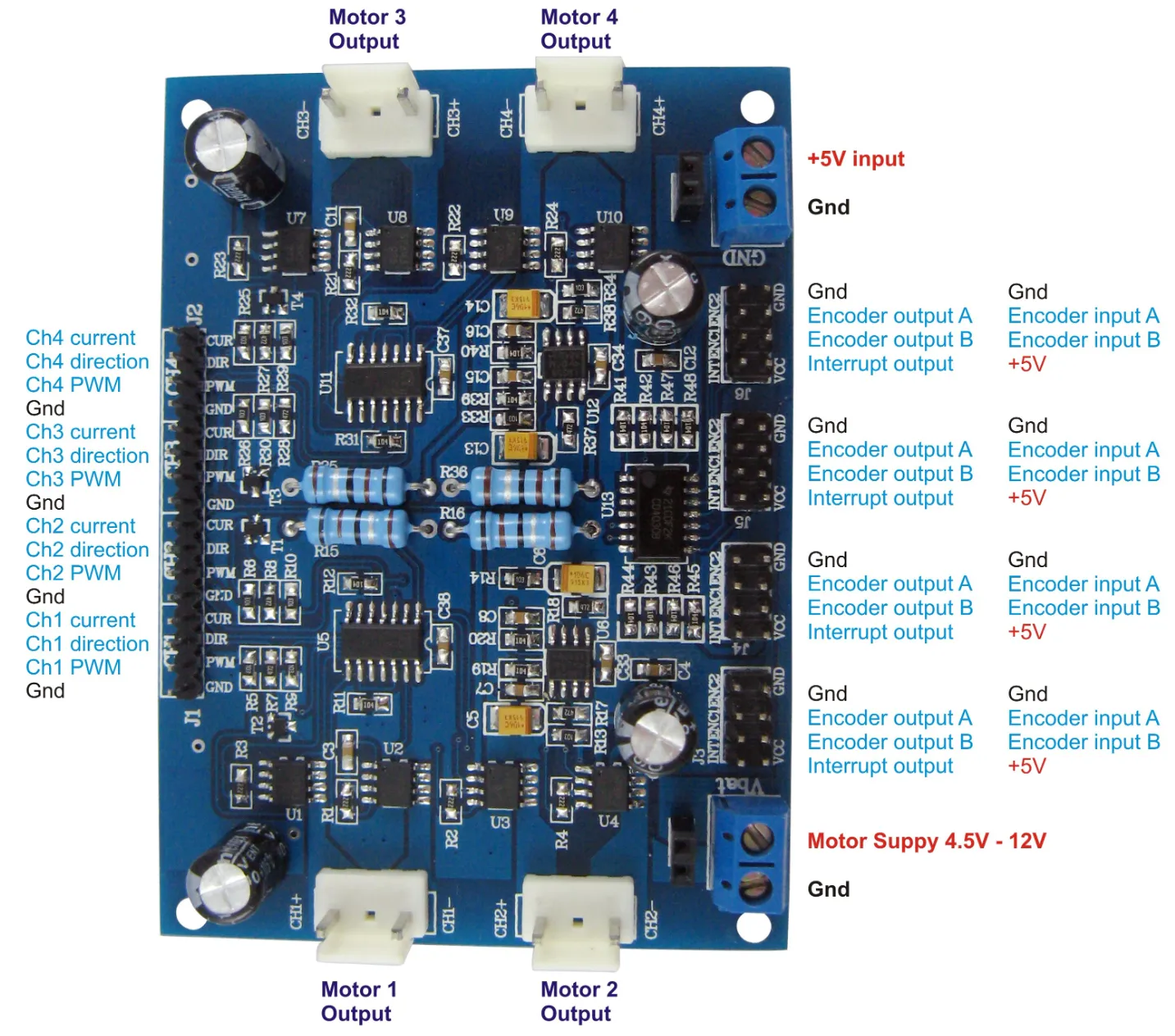
On the left side of the board there are the pins that control the four motors.
- Current – this pin is used to detect over currents. For example when one of the motors is stalled and producing larger currents that could blow the fuse. We will not be working with this pin.
- Direction – this pin tells the driver which direction to spin the motor
- +5v = spin forward
- 0v = spin in reverse
- PWM – this pin tells the motor how fast to spin. We are not going to have variable speed control for this project but if we wanted to we would use PWM and very the pulses to control the speed.
- +5v = 100% power
- 0v = 0% power
Here is a graphic showing the different combinations of the **direction **and **PWM **pins for CH1 = motor 1
Motor spin direction
For the tank to move the motors need to spin in different directions to perform different maneuvers. Here is a chart showing the motor directions. Note that M1 and M3 always spin in the same direction. The same is true for M2 and M4
Conclusion
We have looked at the different signals that we will be dealing with in this project. To drive the tank we will need to take the signal from the receiver and determine which way to spin the motors. Then generate a signal with the Arduino that tells the motor controller which direction to spin the motors to perform the desired maneuver.
Previous: Part 2 - Powering the Machine
Next: Part 4 - Programming the Arduino