Part 2 – Powering The Machine
1: Intro
2: Power
3: Signaling
4: Program
5: Sound The Alarm
Abstract
When thinking about all of the requirements to power a system there are many things to take into account. For this project four of the main ones are
- The Battery
- How much power is it rated to output
- The Arduino
- Get an estimate of how much the board will be drawing during usage
- The RC Receiver
- The Motor Controller Board and Motors
The Battery
During designing it can be a good idea to first look up or measure what the expected loads are and then select a battery that will best handle the requirements of the system. For this project the battery was selected before that, mainly because it was one that I already had.
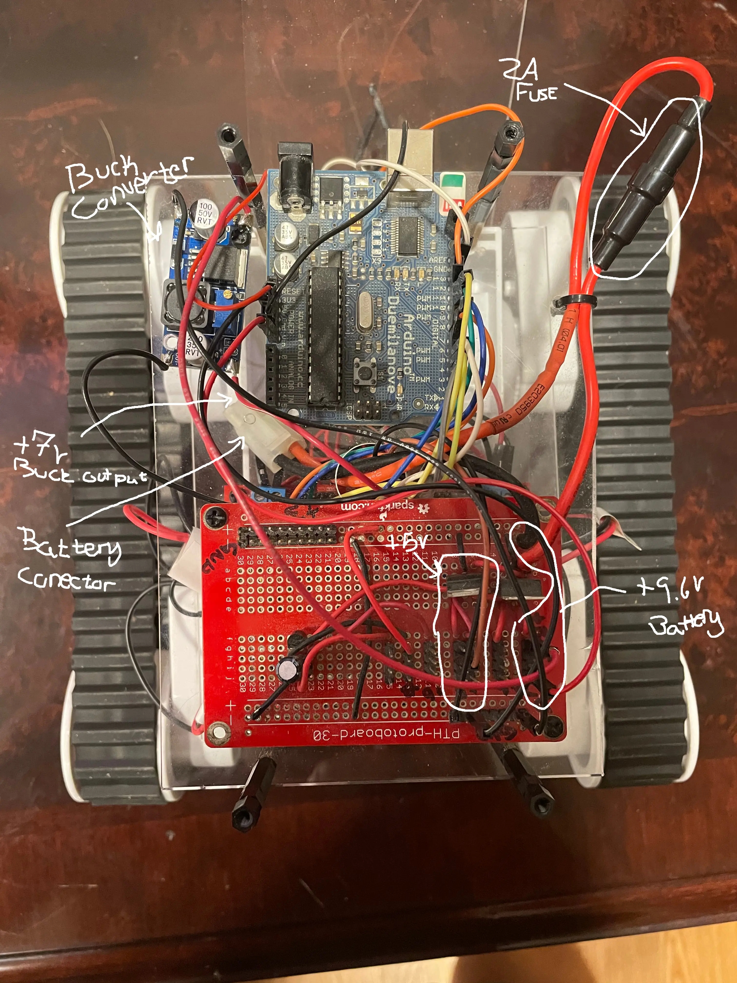
The battery being used for this project is a Tenergy NiMH 9.6v 2000 mAh 1C battery.
According to the datasheet, in section 4-4-3, this battery is rated to discharge at 2A (2000mA) giving the battery a 1C rating. Therefore, regardless of what is connected to the battery putting a 2A fuse on the battery connector should protect the battery from having too large of a load connected to it. Meaning, even if the system tries to draw more than 2A of current from the battery the fuse will open instead of the battery trying to supply more current than it is rated for.
I am going to be using some tube fuses that I have had for a while but here is a link to an assortment of tube fuses that include 2A fuses, all rated at 250V (at least that is what the description says at the time of this writing). The voltage rating on tube fuses shows what voltage that, after the fuse has blown, the fuse can handle until the electricity starts arcing across the gap. The battery in this case is a 9.6V battery so we are good.
It is important to note that just because a fuse was selected that will protect the battery from being used outside of the battery’s ratings it does not mean that the devices that are connect to the battery are protected. For example, if a device is connected to the battery voltage 9.6V and is drawing 1A but can not handle this amount of power. Than, with nothing to limit the current, the fuse will not blow and the connected load will be damaged or destroyed. It is even possible to start a fire so caution is needed here.
The Loads
For this project their are four primary loads
- Motors
- Motor Controller Logic
- Arduino
- RC Receiver
In order to see if the battery setup is capable of running the loads during normal operation a power budget needs to be created.
Motors
- Rated Voltage: 5 – 7.5v
- Supplied Voltage: 7v via buck converter
- No Load Current: 160mA
- Stall Current: 2.5A
For this project the Rover 5 tank chassis has been selected and is supplied with four DC motors.
According to the rover data sheet the stall current for the motors is 2.5A. This means that if the motors are stalled, the tanks treads are stuck on something and at full throttle for example, the motors could draw over the 2A fuse on the battery and cause it to blow. So, if while driving the tank and the treads gets stuck then the tank looses power the first thing to check would be the fuse.
The no load current is how much current is needed to get the motor to spin with nothing connected to the shaft. I was not sure how much power the motors drew so I measured the total current draw of the entire system while driving forward it was about 900mA. Other measurements let me to believe that everything but the motors draw about 100mA leaving 800mA for the four motors. That makes about 200mA of current draw per motor when driving on hard wood floors.
I tested the actual stall current by putting the ammeter in place of the fuse and held all the motors to see what kind of current draw would happen. I got 5A of current with all the motors stalled. Next to ensure that our fuse was in fact protecting the battery I put the fuse back in and stalled all the motors. Sure enough the fuse blew! So we can be sure that at least no more than 2A will flow. Giving us a max power out put of 19.2w (9.6v at 2A = 19.2w)
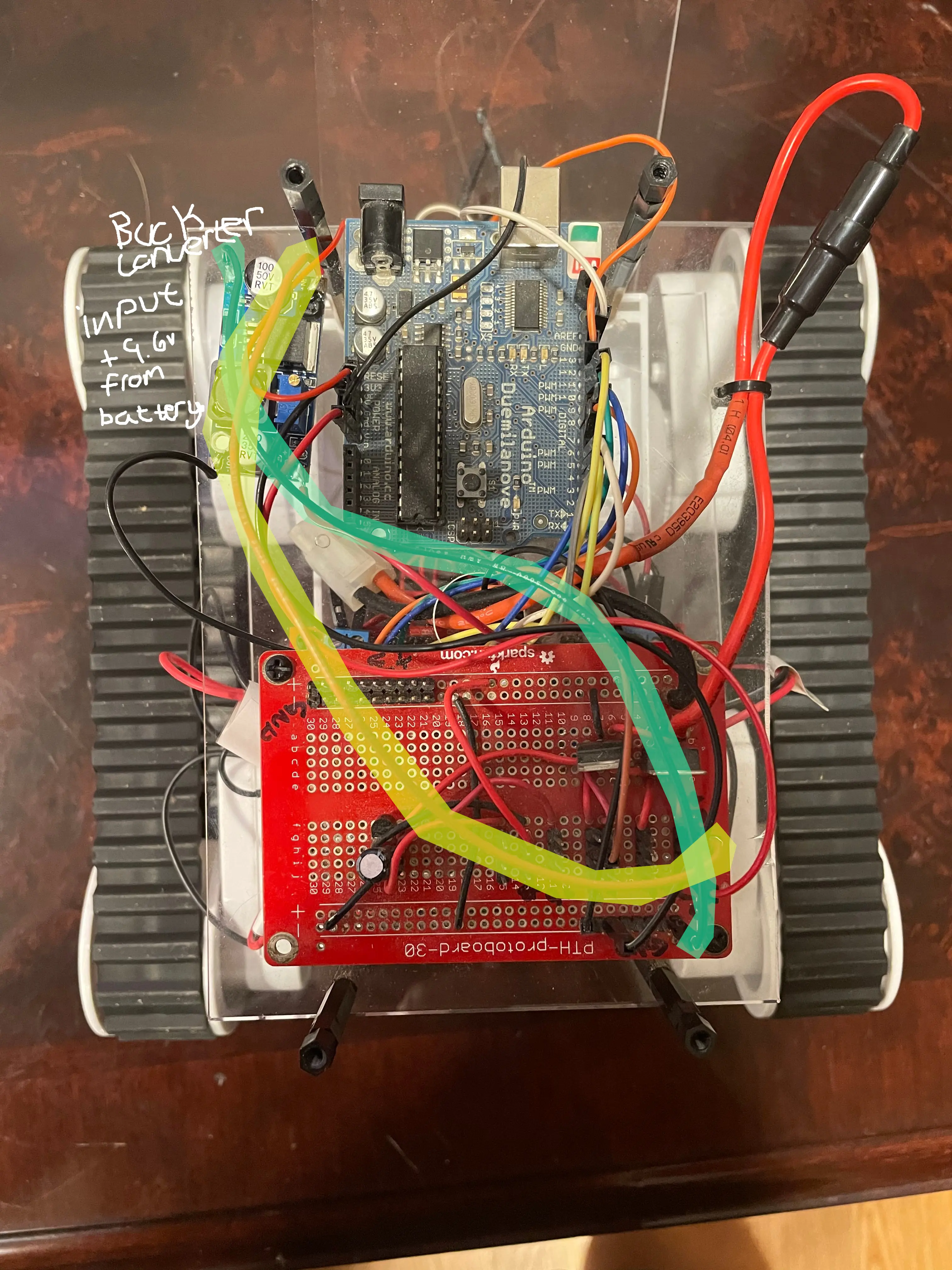
In order to regulate the 9.6v from the battery down to the 7v rating of the motor I used a buck converter instead of a linear regulator. A linear regulator is easy and would work but it is very inefficient. With linear regulators they basically act like resistors and burn up the power that is being regulated out in the form of heat. That is just wasted energy and they get very hot if too much power is being regulated.
Ex: Given a 12v power supply that needs to be regulate down to 5v to supply a 1kΩ load. The DC power equation is P = V^2/R. So the load will consume 25mw (5v^2/1kΩ = 25mw) of power and the regulator will give off 49mw (7v^2/1kΩ = 49mw) of power as heat. That means that most of your power is being burned up as heat to supply the load with the voltage that it needs.
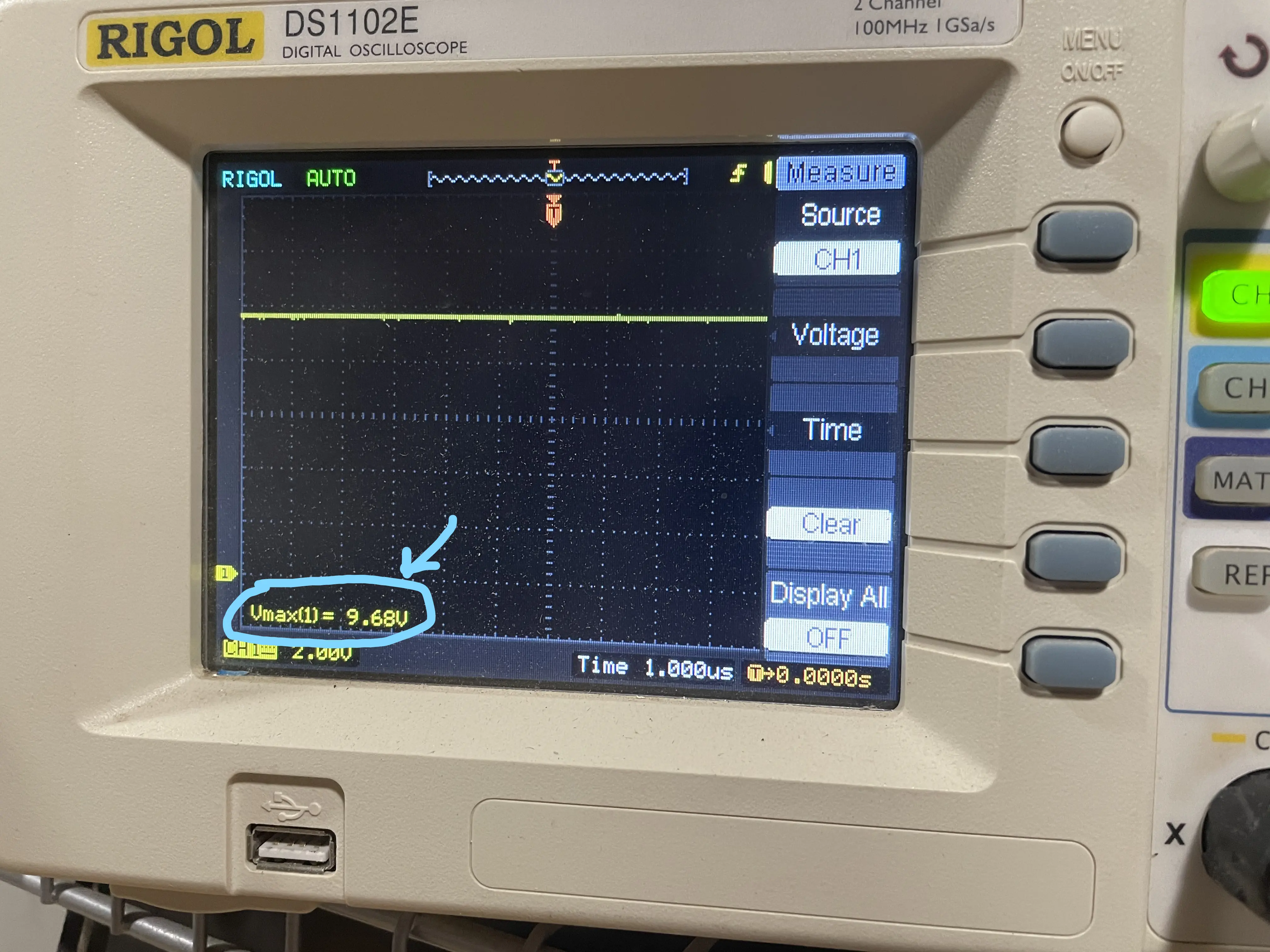
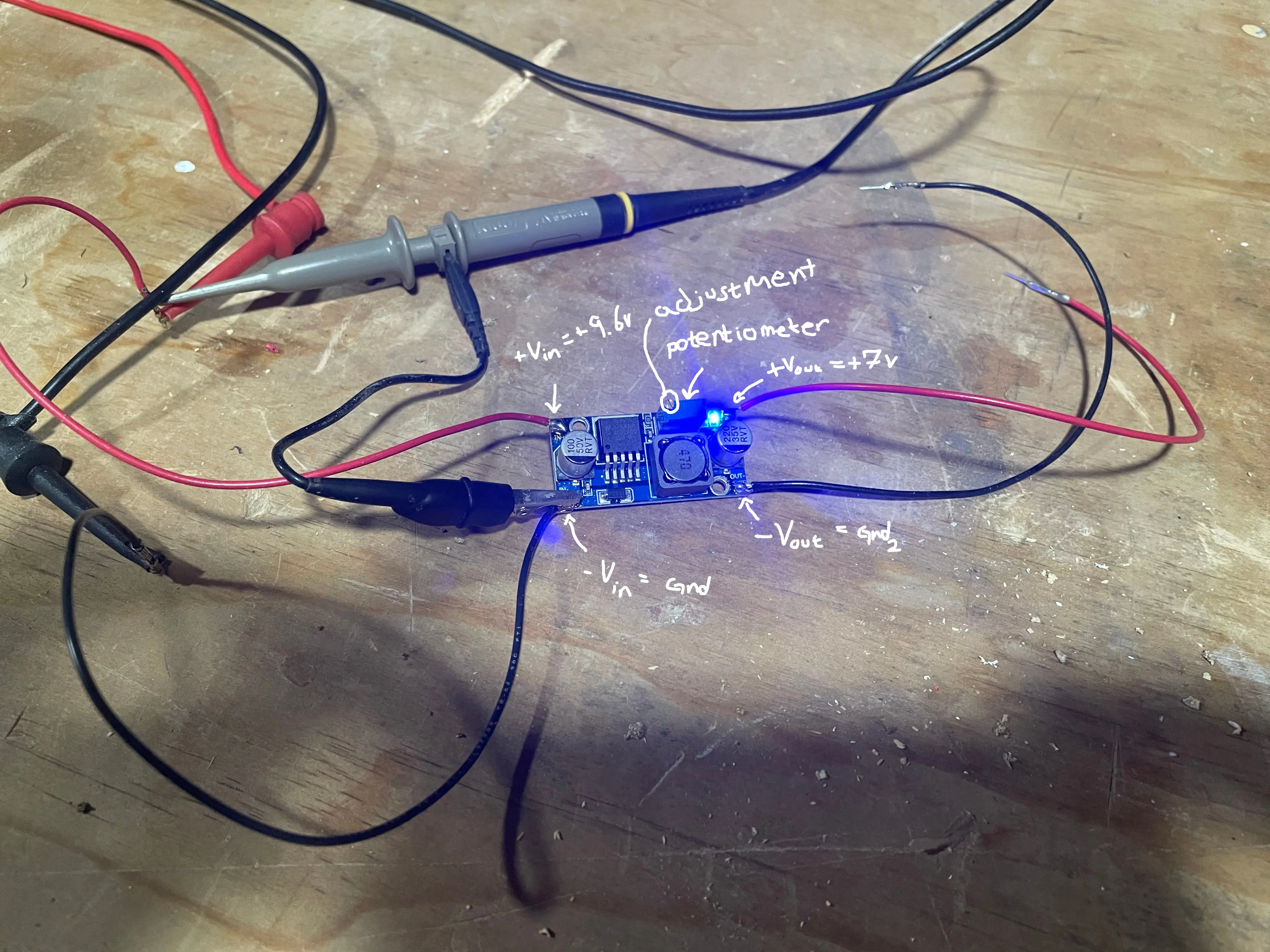
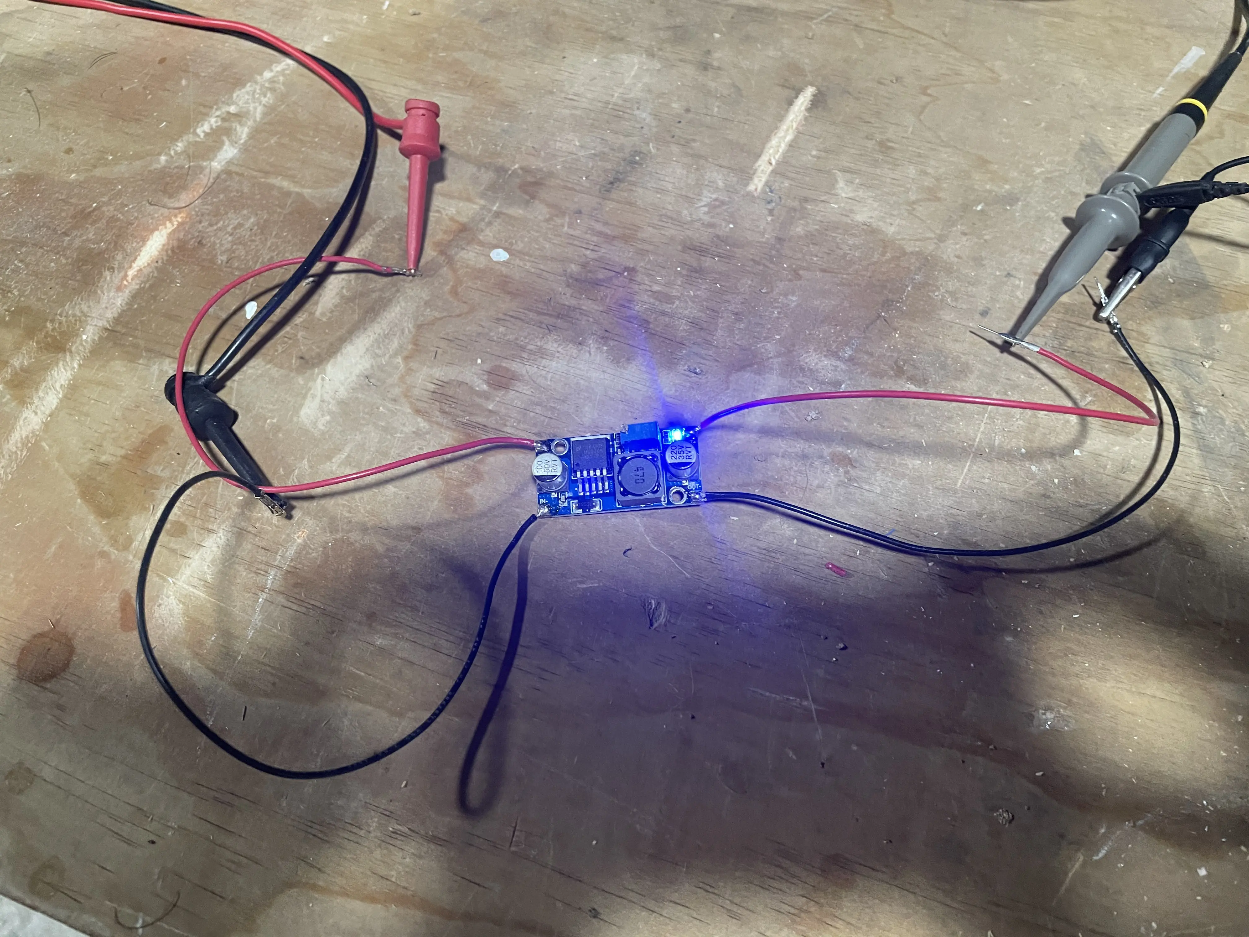
Instead of using a linear regulator to power the motors I used a type of switch mode power supply called a buck converter. These things basically work buy turning on and off really quick so that it only supplies the voltage needed on the other end with out wasting all that power. I adjust the voltage by turning the little golden screw on the dark blue potentiometer that is just to the left of the blue LED on the buck converter. I had to turn counter clock wise quite a few times before it started regulating the voltage down.
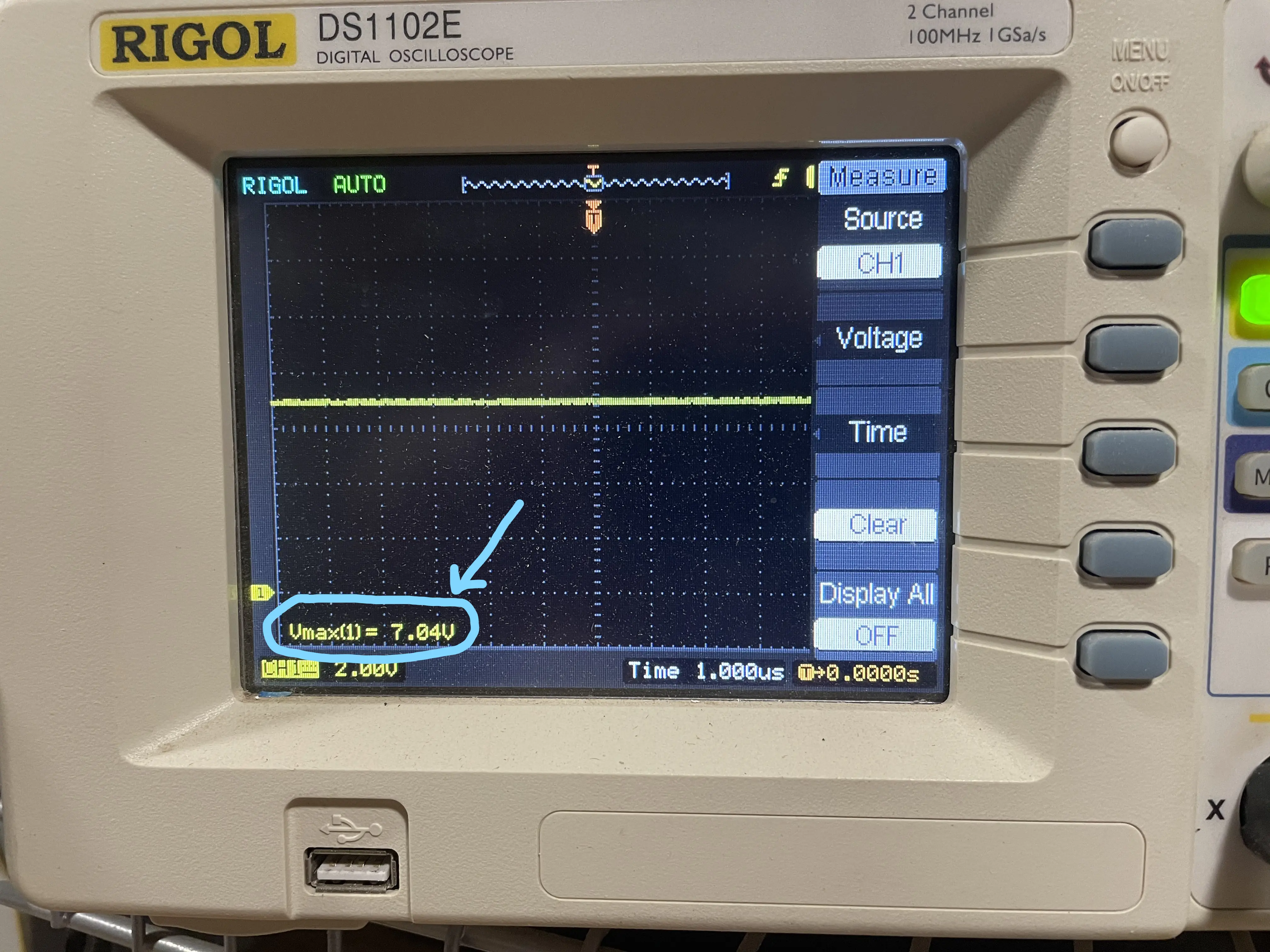
 measuring the output voltage at 7.04v
Motor Controller
- Rated Voltage: 5v
- Supplied Voltage: 5v via linear regulator
- 10mA (measured)
The motor controller data sheet did not specify current draw so I measured it at 10mA
Arduino
- Rated Voltage: 7-12v
- Supplied Voltage: 9.6v directly from the battery
- 50mA (estimate)
Calculating how much power a micro-controller will draw changes based on what features are being used. For example, according to the Arduino web sight, the Duimilinova is capable of supplying 40mA per I/O pin. So the more I/O pins that are outputting the more current the Arduino will draw. However, just because the I/O pin can supply 40mA of current dose not mean that it is. I assume because that because the I/O pin is just being used as a signal to the motor controller that there is minimal current flowing. Based on what others have said the Arduino draws about 30mA while processing. So round that up to 50mA to account for the processing and I/O pins I think this is a decent rough estimate of the current draw. The big concern here is that if too much power is supplied to the Arduino that it damages the board, luckily the Arduino has an onboard voltage regulator that is capable of handling the battery voltage.
RC Receiver
- Rated Voltage: 4.0 – 8.4v
- Supplied Voltage: 5v via linear regulator
- 60mA (measured)
The specs for the FS-iA6B did not include the current consumption so I measured the current with my ammeter.
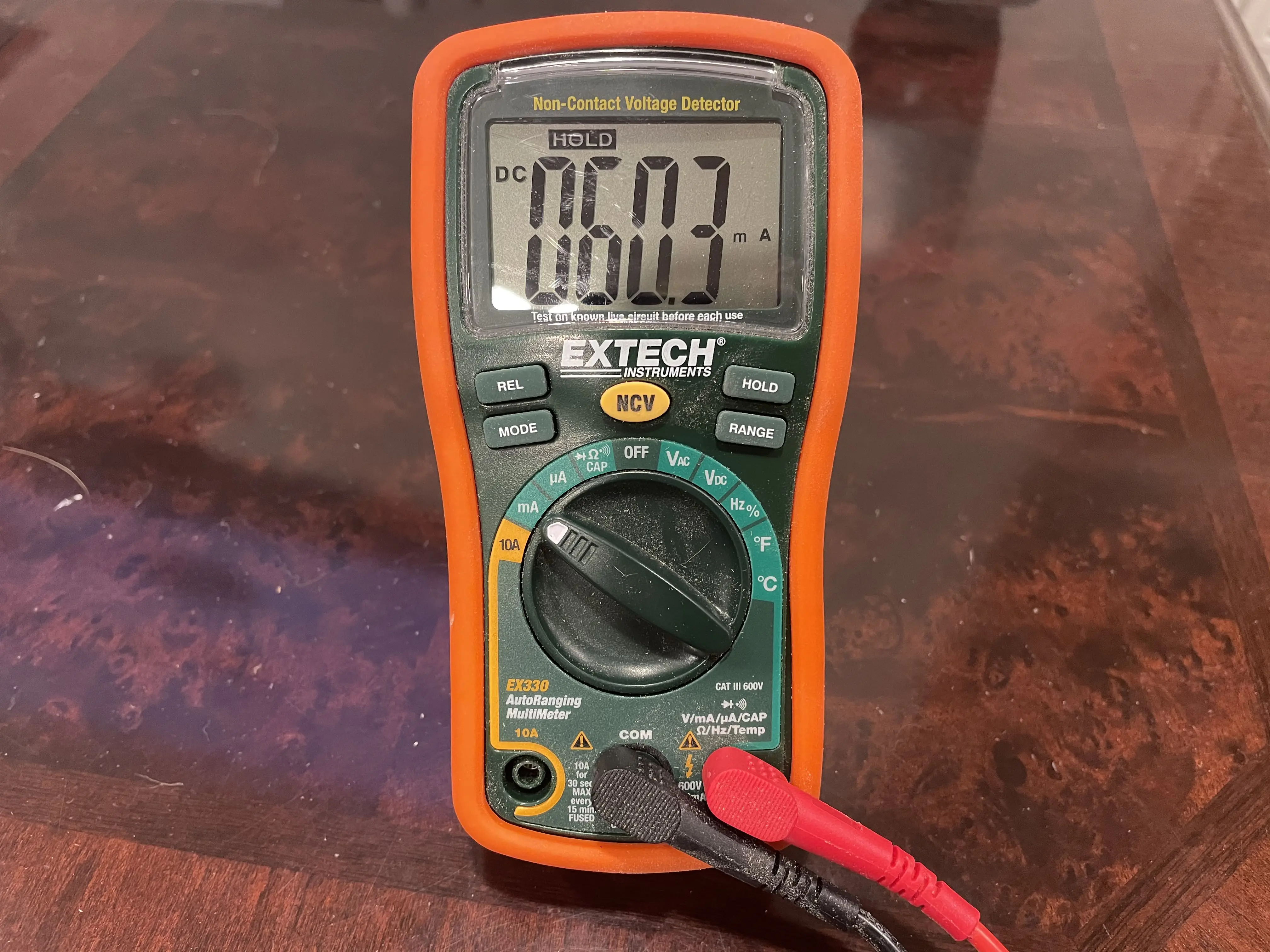 FS-iA6B current measurement
Power Budget
- Pbatt = 19.2w
- 9.6v * 2A = 19.2w
- Parduino = 480mw
- 9.6v * 50mA = 480mw
- Prc_reciever = 300mw
- 5v * 60mA = 300mw
- Pmotor_controller = 50mw
- 5v * 10mA = .05w
- Motors
- 7v * 200mA * 4 = 5.6w
120mA should be what the current draw when powered on but not moving is however I measured the actual value to be about 75mA.
Power Regulation
There are 3 voltages needed for this project
- +9.6v
- +7v
- +5v
The +9.6v is the battery voltage.
The +7v is created by regulating the battery voltage with the buck converter. This supplies the motors
The +5v is created by an LM7085 in a TO220 package and is supplied by the battery. This power source is used to power the motor controller
I have a board I previously made that has a few linear regulators on it that I will be using. For this project I am only using the +5v rail powered by the LM7805.
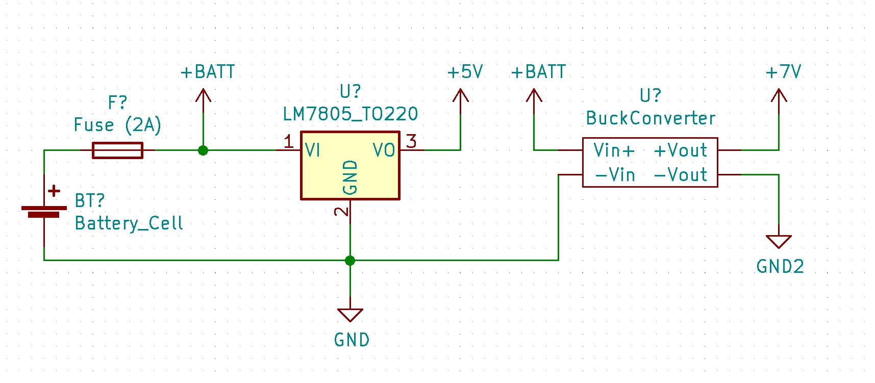 Wiring diagram of the power supplies
Conclusion
It is definitely possible to draw more current than the battery is rated to handle. Protecting the system with a 2A fuse is what I have selected to keep the battery safe. So if when driving around and the motors meet some resistance then the system looses power…its probably the fuse.
Previous: Puppy Patrol MK1 - Intro
Next: Puppy Patrol MK1: Signals and Controls