How Diodes Work
Simple Answer
Diodes work by allowing current to flow in one direction but preventing current from flowing in the opposite direction (except in some special cases)
More in depth answer
How diodes are created
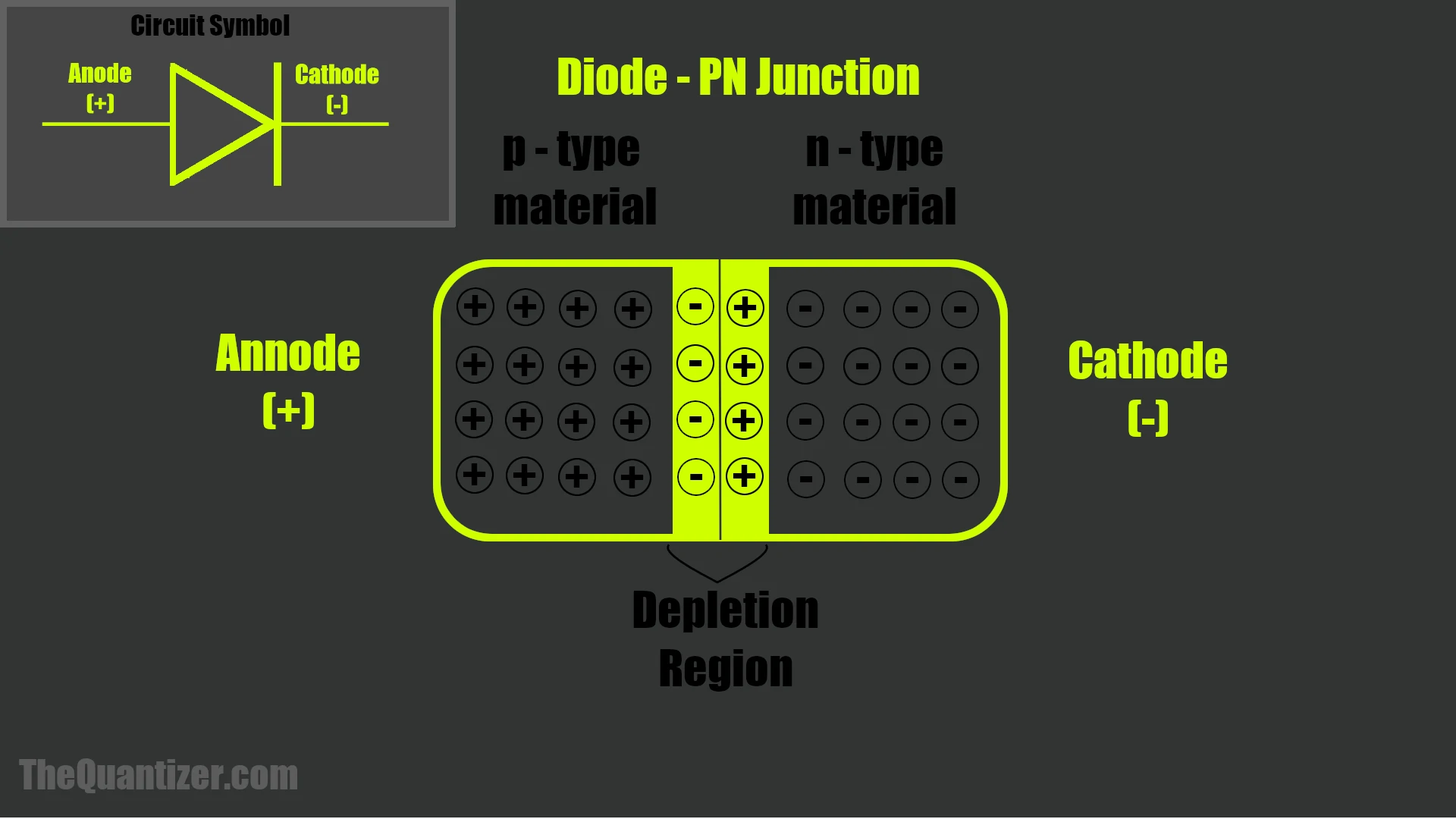
Diodes are created by taking a positively charged piece of silicon (p-type) and a negatively charged piece (n-type) and putting them together. This will form a p-n junction. When you create this pn junction some of the electrons in the n-type material flow into the p-type material because they are attracted to the positive charge. When these electrons flow into the p-type semiconductor they leave holes at the edge of the n-type semiconductor making it have a slightly positive charge. This continues until the positive charge at the edge of the n-type material is large enough it starts attracting the elections back. Once the positive charge in the n-type material is equal to the negative charge being felt by the electrons in the p-type material a balance of charge will occur.
The negative charge in the p-type material comes from the electrons that flowed from the n-type to the p-type. Furthermore, the positive charge is created by the holes left by the electrons as they moved from the n-type material to the p-type material.
This junction is called the depletion region and that is the basis of how a diode is created.
How diodes work
Once a positive voltage source is applied to the negative side of the diode (n-type side) this will collapse the depletion region and allows electrons to flow freely. This is known as forward biasing a diode. However, if the charge is reversed (reverse biasing) the depletion region grows and prevents current for flowing in the opposite direction. This is the basics of how a diode works by allowing electric current to flow in one direction and not the other.

What are diodes used for
The ability of diodes to allow for current in one direction but not the other allows for the creation of all kinds of useful circuits.
- Reverse current protection - Diodes can be used to prevent someone from plugging in something backwards providing reverse current protection.
- AC to DC conversion - Diodes can be used to take an AC current and redirect both cycles so that they both flow in the same way across a load. This is called a rectifier and is often used to turn an AC signal into a DC signal
- LEDs - Diodes can emmit light allowing for all kinds of cool applications, like indication status or displaying information like volume levels.
- Voltage Regulation - A special kind of diode called a Zener diode is made to be plugged in backwards (reverse biased if you want to be technical) and has the cool property of providing a stable voltage output, thus providing voltage regulation.
- Flyback Diode - A diode used to dissipate the current caused by the inductive nature of DC motors.
Types of diodes
- Power diodes
- Light-emitting diodes
- Schottky diodes
- Zener diode
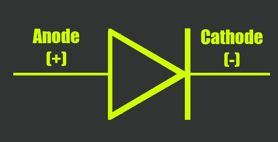
Annodes and Cathodes
Some terminology used in association with diodes is annodes and cathodes. The are just was of indicating what end of the diode you are talking about. The positive terminal is the annode. Where as the negative terminal is the cathode. This means that for a forward biased diode the current flow (conventional) goes from annode to cathode.
Reverse biasing a diode
If a positive voltage is applied to the negative side of a diode than the depletion region will grow thus blocking current from flowing in this direction.
This causes the diode to act like an open circuit and is known as reverse biasing a diode.
Preventing current flow in the reverse bias direction is a useful property of diodes however, one thing about reverse biasing is that the depletion region can not grow indefinitely.
Eventually the depletion region will grow large enough that it consumes the entire p-type and n-type material reaching what is known as saturation.
At this point the diode is no longer able to prevent the flow of current and current will flow in the opposite direction.
This sounds like a bad thing and in mose cases it is.
However, there are some smart people out there that took advantage of this characteristic and created diodes that are meant to operate in revers allowing them to work as voltage regulators.
These are zener diodes

AC to DC conversion
A tried and true way for power supplies to convert AC (alternating current) to DC (direct current) is by using four diodes to create a full wave bridge rectifier.
This device basically controls the flow AC current so that all of the peaks go in one direction creating what we call ripple DC.
All you need next is a hook up a capacitor to the output of the rectifier so that it can charge up and resist a change in voltage.
Bam! you have just converted an AC input into a DC output using four diodes and some capacitors…pretty 🆒.
If you for some reason don’t like the negative half of an AC signal and instead want to only use the positive side than you are in luck. For half the amount of diodes you can get half of the signal using a half-wave rectifier. This is exactly what it sounds like, it uses two diodes instead of the four from the full-wave rectifier and only outputs a half-wave. The positive half or negative half depending on how it is hooked up. The result is instead of consecutive series of humps on the output of the rectifier you get ever other hump. Just like the full wave variant, if you put enough capacitance on the output of this circuit it will smooth out those humps and turn it into a DC output. Also, using a half wave rectifier can be a useful way to count the frequency of an AC signal. For example, you can feed the half wave signal into a circuit that will count up when a voltage threshold has been crossed. This will result in a count up for every cycle thus allowing you to measure the frequency of the AC input.
Reverse current protection
Diodes are also used to prevent current from flowing in the wrong direction in a circuit.
Typically, we use power diodes to do this because they are built to allow more current to flow through them in the forward bias direction.
One thing to note about power diodes.
What ever magic they need to pack in to them to allow for the high current capabilities causes them to drop more voltage, around 1.1v (2n4001 [look for forward voltage drop])
Take a look at the following example to see how reverse current protection is achieved with a power diode.
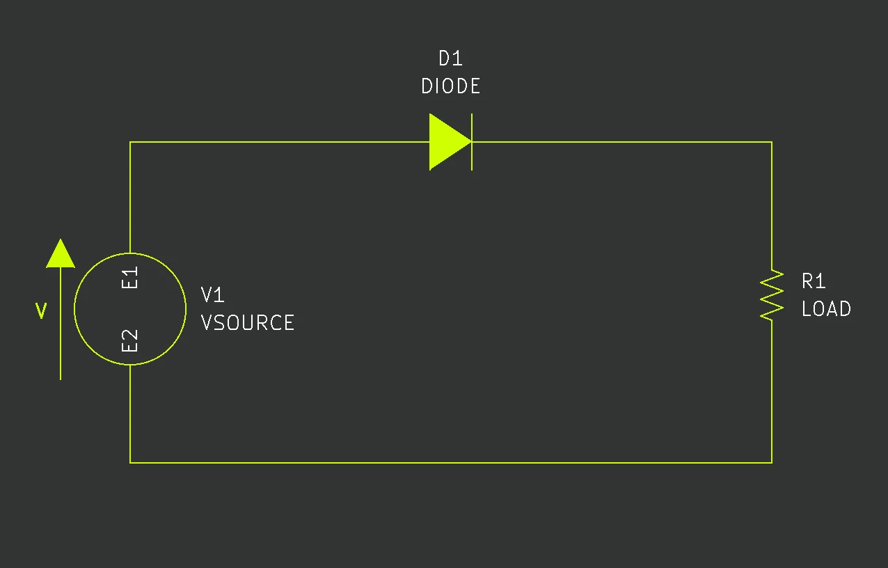
In the above circuit you can see that if someone plugs the power into the circuit in the wrong direction the power diode will be reverse biased and prevent the current from flowing. Simple fix to a potential destructive problem for electronic devices ⚡
Voltage regulation
Most diodes are meant to be forward biased and if reverse bias they will block current flow…that is true for most but not all diodes. In fact, Zener diodes are meant to be reversed biased. This is because Zener diodes are engineered to reach zener breakdown voltage (saturation) and conduct in the reverse bias direction. When reverse biased the Zener diode will maintain a fairly consistent voltage across it over a wide range of voltage inputs. Here is an example, imagine that we have a circuit containing a resistor in series with a Zener diode designed to reach breakdown at 3v. Then we supply 5v to our circuit. This will result in the Zener diode conducting in the reverse direction and have a voltage drop across it of around 3v and the series resistor drops the other 2v. Additionally, if the input is increased to 10v than the Zener diode will still drop around 3v and the series resistor will drop 7v. That is how we use Zener diodes as voltage regulators.
Light Emitting Diodes (LEDs)
You have no doubt see these bad boys before. They are the things producing most of the flashing and solid lights you see in your electronics. These work in the same fashion as most other diodes but have been engineered to produce different color lights than to be used to control current flow or in full wave bridge rectifiers…though that would be kind of cool to see. Imagine a low frequency AC signal that you could detect with your eyes flowing through LEDs…maybe we should build that.
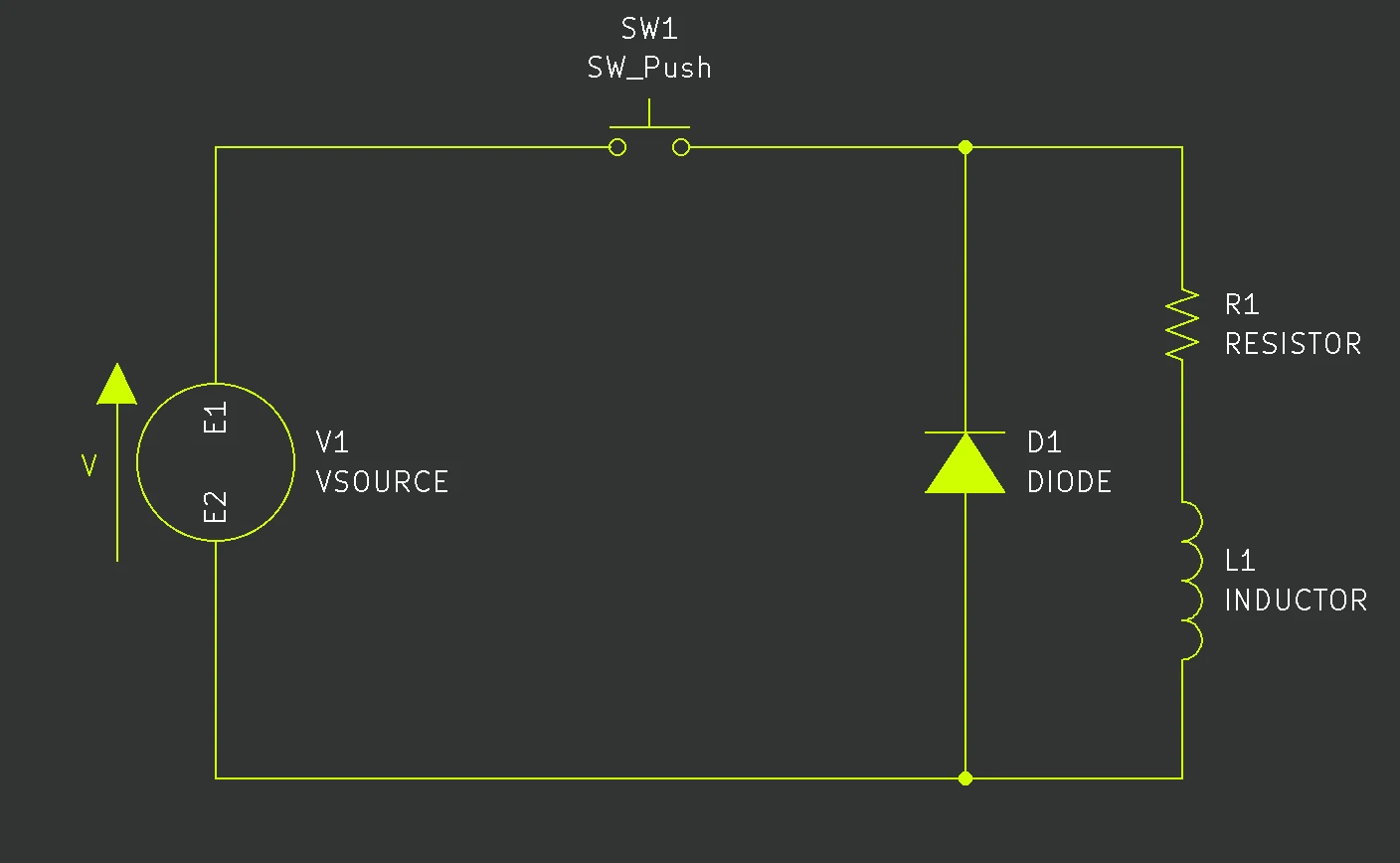
Flyback Diode
When using a DC motor in an electrical circuit it has both a resistive property and an inductive property to it. Why does this matter? Well when current flows through an inductor it builds a magnetic filed while the current is flowing. Once the applied voltage is removed the magnetic filed will collapse inducing a current in the circuit. A common way to deal with this current that flows after the power is shut off is to put a diode in parallel with the DC motor. What this flyback diode will do is provide a path to dissipate the flow of electrons that is induced by the collapsing of the magnetic filed built up in the motor. Problem solved!