Part 5 – The Final Step…SOUND THE ALARM!
1: Intro
2: Power
3: Signaling
4: Program
5: Sound The Alarm
Abstract
So far we have the Puppy Patrol MK1 moving by remote control and now its time to add the final touch. SOUND THE ALARM! In this section we are going to make the Puppy Patrol MK1 blast an alarm when we flip a switch on our transmitter.
Producing The Signal
The Arduino Duemilanove is not capable of outputting an analog signal so we needed to find a way of using a digital output and convert it so that an audible tone would be produced on a speaker. We ultimately decided to use, because it was simple, a low pass filter to converting a PWM signal into a sin wave. This works by using an RC network that will be charging as the on pulses of the PWM signal are active and discharging when they are off. If you space the PWM signal appropriately it will produce a rough sin wave. For more information about PWM and designing the low pass and high pass filters go here:
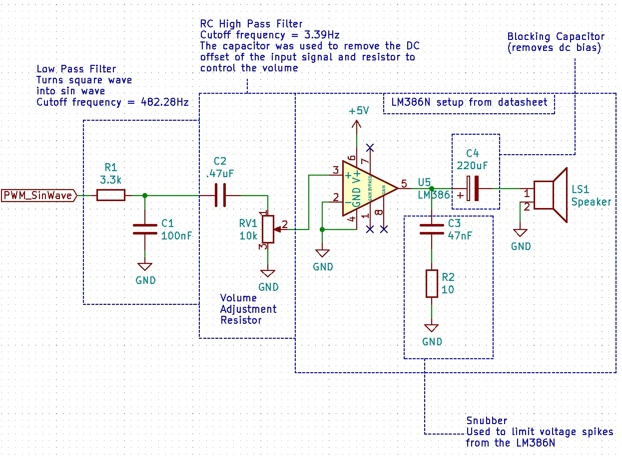
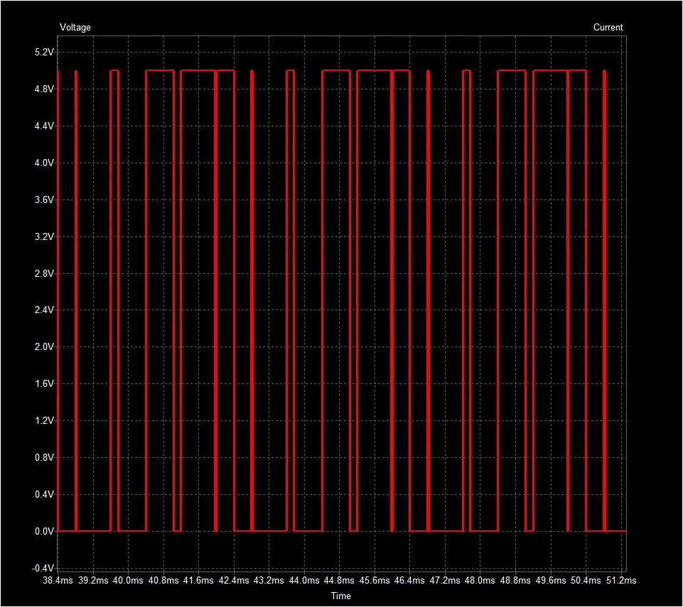
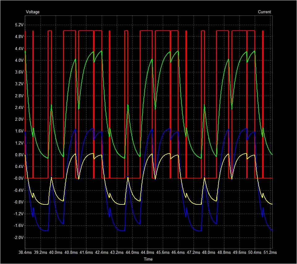
First we start with the PWM input into the circuit
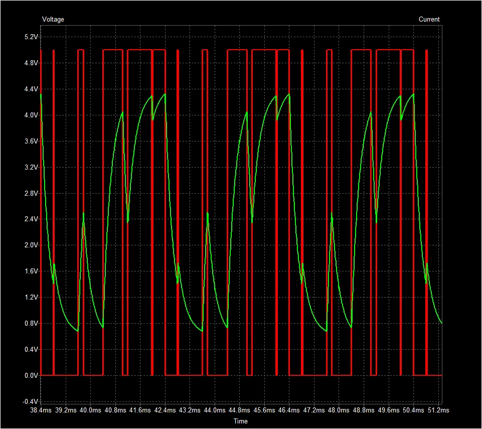
Next, the signal is passed through the low pass filter and produces a rough sin wave with a DC offset. Meaning, the sin wave does not alternate from positive to negative voltage but instead is alternating from a higher positive voltage to a lower positive voltage. (green signal)
Now we want to oscillate around zero so we added blocking capacitor. You can think of a capacitor in series with a signal will block the DC parts of the signal while the AC parts will pass through. (blue signal)

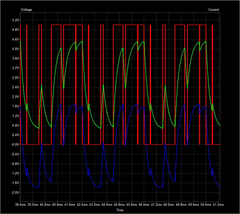
Finally, the signal goes through a potentiomoter that we use as a volume control for the Puppy Patrol MK1. (yellow signal)
Now that we have a our tone oscillating around 0 we cant just pass that to a speaker for several reasons.
- If we connected an 8ohm speaker to the output of the potentiometer than it would effectively short out the potentiomerter and it would no longer work as a voltage selection.
- If we removed the potentiometer and used the 8 ohm speaker instead we would affect the filtering characteristics of the high pass filter and not get the output signal we wanted. Also, minimal power would be flowing through the speaker so you would probably not be able to hear anything.
- The reactance (you can think of reactance as the resistance value for capacitors and inductors when using an ac signal) of the .47uF capacitor at 250Hz is 1/(2*pi*250*.47u) = 1355 ohms and this is so much larger than 8 ohms. Meaning that if we wanted 1w to go to the speaker we would have to supply 169 watts to the high pass filter so that 1w would make it to the speaker! Everything would be on FIRE if we tried that!!!
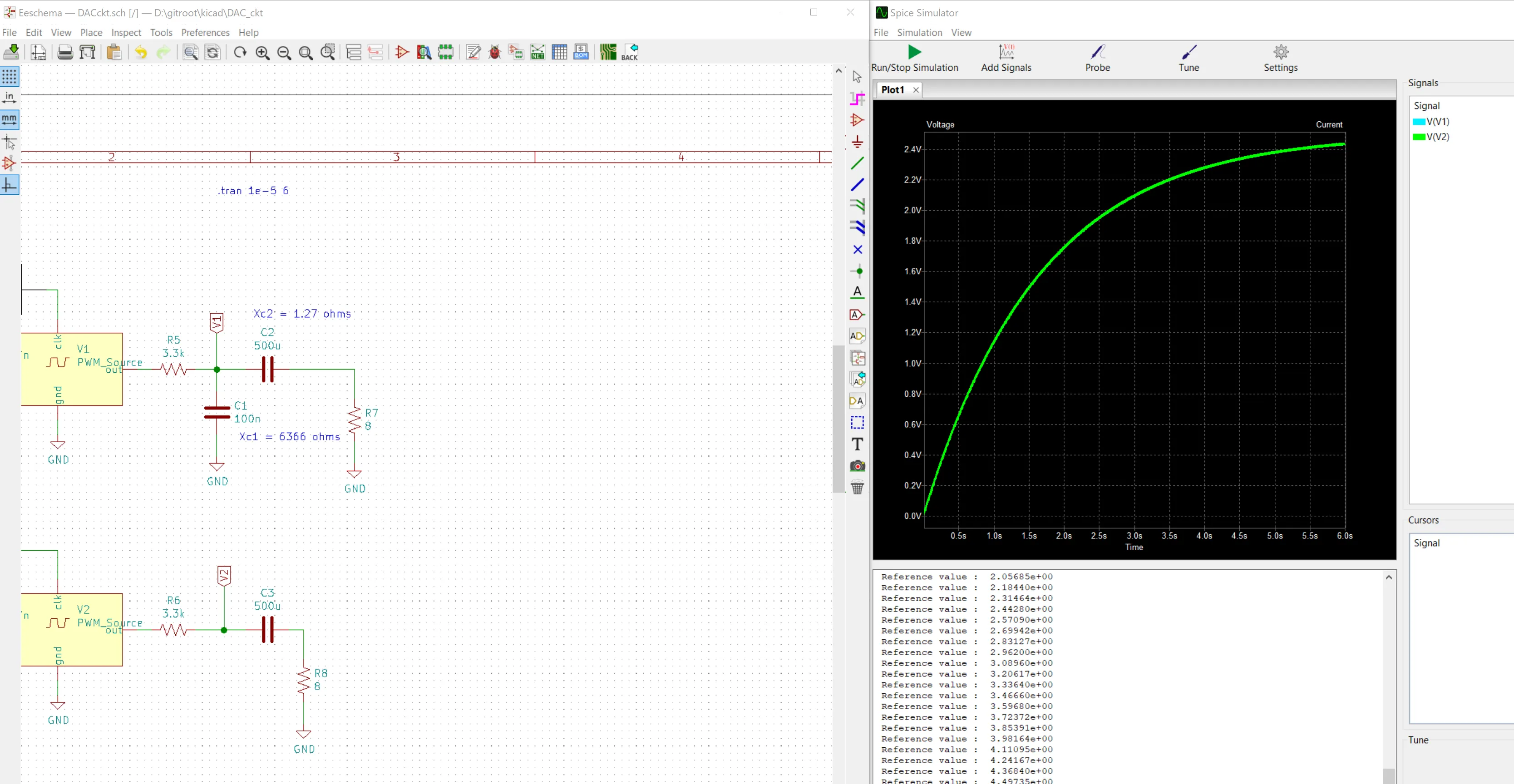
- If we then increase the capacitance value of the high pass filter in order to bring the filter back to the same knee frequency and not burn up so much power it would require us to change the low pass filter values as well. This is because the reactance of our larger 500uF capacitor = 1/(2*pi*250*500u) = 1.27 ohms and the capacitor of our existing low pass filter 100nF capacitor = 1/(2*pi*250*100n) = 6366 ohms. A much larger value. Meaning that our new “high pass filter” has a significantly less reactance that it effectively is a short compared to the 100nF capacitor path. Meaning the 100nF capacitor path is doing almost nothing now as can be seen in the following graph. The difference with the 100nF capacitor in the circuit and with out it is almost nothing. In fact you cant even see the V1 (blue) graph because it is directly behind the V2 (green) graph. Also note how long it takes for the capacitor to charge, around 6 seconds! This is because the RC time constant for 3.3k and 500uF is = 500u*3.3k = 1.65 and we consider a capacitor mostly charged when it reaches 3 time constants 1.65*3 = 4.95 seconds. This is way to long for us to use it to convert the PWM input into a rough sin wave. Furthermore, when you remove the 100nF capacitor you can see the dominate characteristic of this circuit is now a low pass filter!!! You cant see the PWM wave riding the voltage line because this low pass filter has a knee frequency of .1Hz so the AC component has been attenuated greatly. Well that didn’t work 🙁
- Once we update the low pass filter values our output wave form is good! However we will need to deliver around 2A peak at 5v from the Arduino and that is way more than it can supply. It is specked for 5v at 500mA, that is four times less.
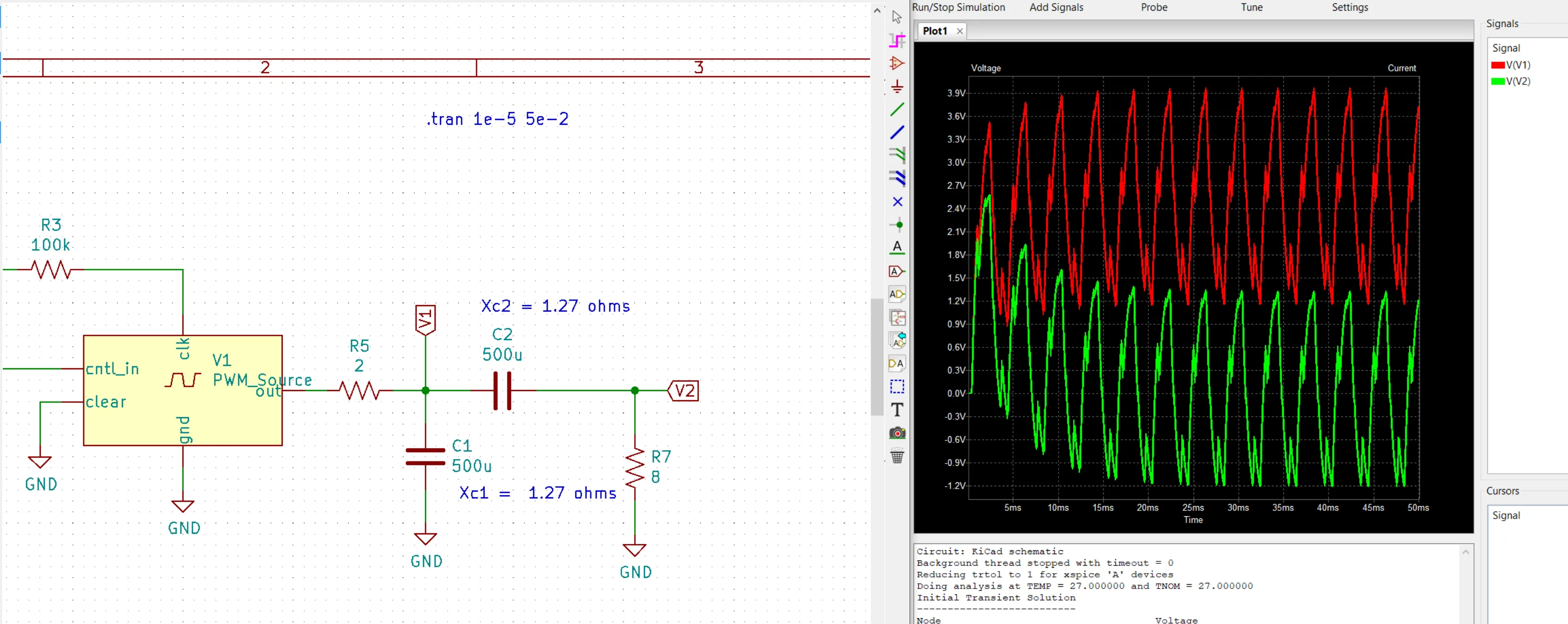
Voltage at V1 and V2
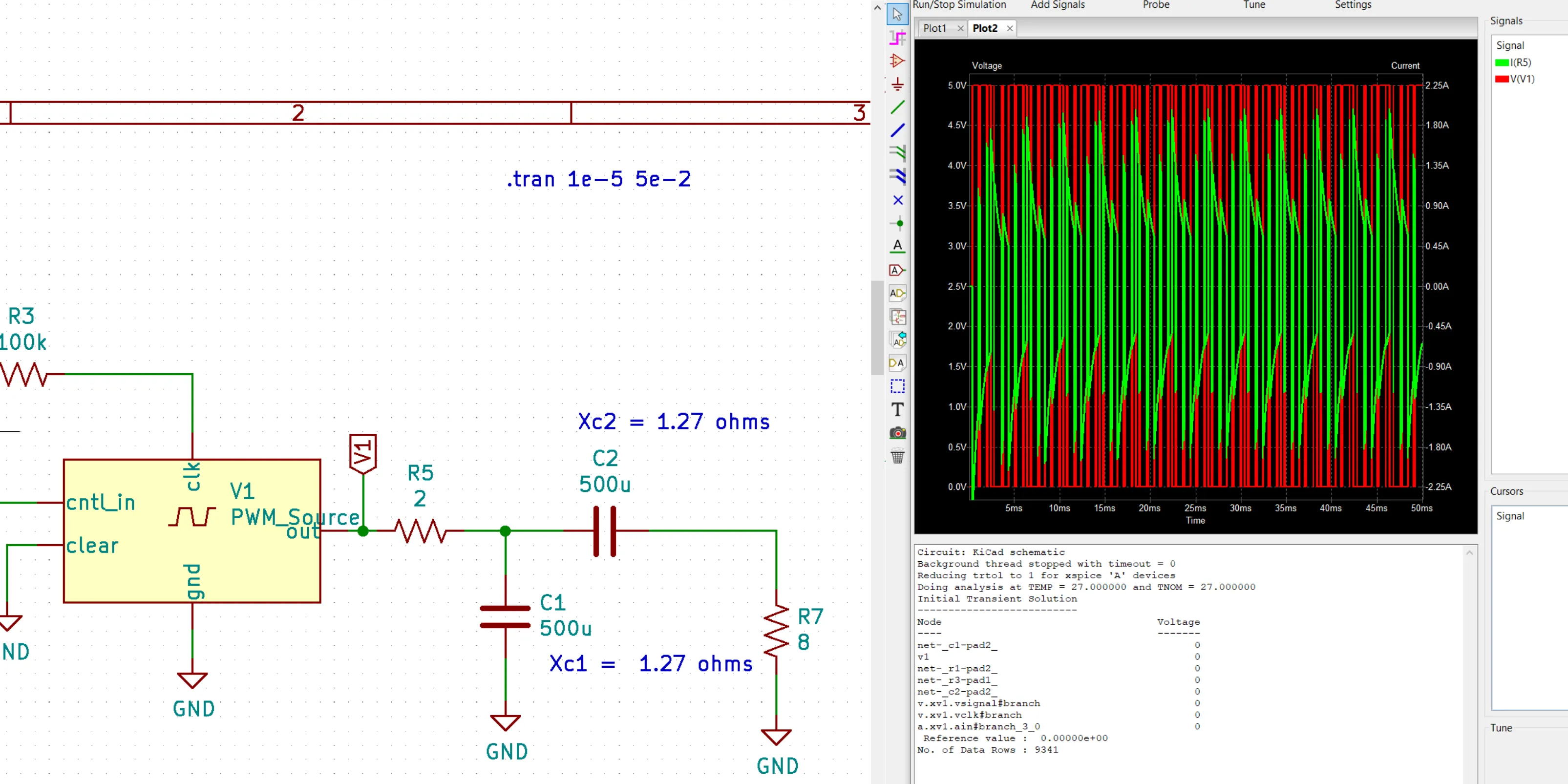 Current and voltage through R5
- You could try and add more resistance to the circuit but that would impact the filters…what a mess.
Basically, if you try to adjust the circuit and then compensate for the cascading impacts it has it just dose not work.
So what we did is add a power amplifier to our circuit that acts like a buffer so that our PWM conversion circuit is minimally affected by connecting the power amplifier (it looks like a really large resistor to our PWM circuit) and the amplifier will produce the same signal but with the ability to drive a speaker. For this project we selected a LM386N because it does what we need, is really common, inexpensive, and comes in a DIP package that is easy to work with.
We finished up the circuit by following the datasheet and adding a 220uF blocking capacitor to remove the DC offset of the signal coming out of the LM386N. Lastly, we added a 47nF and 10 ohm resistor in parallel with the speaker as the datasheet recommends. We are not really sure what this leg is for but from what research we did it looks like it may be something called a Zobel network…don’t know. However, the datasheet recommended it so we put it in the circuit.
And that is it for the circuit, we now have the hardware in place that we need to produce a tone from the Puppy Patrol MK1.
Generating the PWM with the Arduino
First we setup the Arduino to use pin 6 as the PWM output for the audio signal and pin 9 for the input pin to turn on/off the audio by flipping SWB on the FS-i6X transmitter. Additionally, we set the registers on the microcontroller so that interrupt service routine ISR(TIMER1_COMPA_vect) is called every time the counter reaches the value contained in the register OCR1A.
//period of one pwm cycle is 50HZ = .02
//Want to have a timeout that is twice as long as any one cycle should be.
//(1/50)*2/10^-6 = 40000. Then added a fudge factor of 10,000 to bring it to 50,000
//(1/50) = Hz to seconds
// *2 = Twice the cycle
// /10^-6 = seconds to microseconds
#define PWM_TIMEOUT_MS 50000

#define AUDIO_ON_THRESHOLD 1250

#define CH6_SWITCH_B_PIN 9
#define AUDIO_PWM_PIN 6

typedef struct {
  int audio;
} Controls;

Controls NewControls() {
  Controls con = {0};
  return con;
}

#define HIGH_FREQ 16000
#define LOW_FREQ 32000

void setup() {
  Serial.begin(9600);
  Serial.println("Starting puppy patrol");

  noInterrupts(); // disable all interrupts
  TCCR1A = 0;// set entire TCCR1A register to 0
  TCCR1B = 0;// same for TCCR1B
  TCNT1  = 0;//initialize counter value to 0
  // set compare match register for 1hz increments
  OCR1A = HIGH_FREQ;
  // turn on CTC mode
  TCCR1B |= (1 << WGM12);
  // Set CS10 for no prescaler
  TCCR1B |= (1 << CS10);
  // enable timer compare interrupt
  TIMSK1 |= (1 << OCIE1A);

  interrupts(); // enable all interrupts;

  //Recever pins
  pinMode(CH6_SWITCH_B_PIN, INPUT); // Switch B of recever
  pinMode(AUDIO_PWM_PIN, OUTPUT);
}
Next we define the ISR(TIMER1_COMPA_vect) function. If SWB is on than it is executed. While running it will take the values from sinArr2 and send them out AUDIO_PWM_PIN one bit at a time. Then after some time we alternate between setting the counter register to LOW_FREQ and HIGH_FREQ to alternate the tone.
#define SIN_ARR_LEN 2
#define BITS_PER_MESSAGE 1
#define AUDIO_ROTATE_INTERVAL_LOW 125
#define AUDIO_ROTATE_INTERVAL_HIGH 250
int currentBit = 0;
int currentMsg = 0;
//int sinArr8[] = {0b0000, 0b1000, 0b1100, 0b1110, 0b1111, 0b0111, 0b0011, 0b0001};
//int sinArr6[] = {0b000, 0b100, 0b110, 0b111, 0b011, 0b001};
//int sinArr4[] = {0b00, 0b10, 0b11, 0b01};
int sinArr2[] = {0b0, 0b1};
int audioEnabled = 0;

ISR(TIMER1_COMPA_vect) // timer compare interrupt service routine
{
  if(audioEnabled){
    int outMsg = sinArr2[currentMsg];
    int outBit = ((outMsg >> (currentBit)) & 0x01);
    digitalWrite(AUDIO_PWM_PIN, outBit);
    updateBits();

    int static audioDelay = 0;
    int static audioRotateInterval = AUDIO_ROTATE_INTERVAL_LOW;

    //  Serial.println(audioDelay);
    if (audioDelay >= audioRotateInterval) {
      //    Serial.println("Filp frequency");
      if (OCR1A == HIGH_FREQ) {
        OCR1A = LOW_FREQ;
        audioRotateInterval = AUDIO_ROTATE_INTERVAL_LOW;
      } else {
        OCR1A = HIGH_FREQ;
        audioRotateInterval = AUDIO_ROTATE_INTERVAL_HIGH;
      }
      audioDelay = 0;
    }
    audioDelay = audioDelay + 1;
  } else {
    //Turn off output otherwise capacitors will charge and cause a delay when audio is turned on.
    digitalWrite(AUDIO_PWM_PIN, 0);
  }
}


void updateBits() {
  if (currentBit > 0) {
    currentBit = currentBit - 1;
  } else {
    //Just read the final bit => reset the count
    currentBit = BITS_PER_MESSAGE-1;
    if (currentMsg < SIN_ARR_LEN - 1) {
      //Read the next byte
      currentMsg = currentMsg + 1;
    } else {
      //Read the final message so restart the buffer
      currentMsg = 0;
    }
  }
}
Lastly, we write the main loop to check the receiver to see if SWB has changed state. There are more functions here than are necessary to do what we need but it will make since when we combine Puppy Patrol MK1’s direction controls
void loop() {
  Controls con = readControls();
  if(con.audio == 1){
    audioOn();
  } else {
    audioOff();
  }

  delay(100);
}

Controls readControls() {
  static int audioChan;
  Controls con = NewControls();

  //This will block while trying to sample a pulse
  audioChan = pulseIn(CH6_SWITCH_B_PIN, HIGH, PWM_TIMEOUT_MS);

  if (audioChan < AUDIO_ON_THRESHOLD) {
    con = setAudioOff(con);
  }
  else {
    con = setAudioOn(con);
  }

  return con;
}

Controls setAudioOn(Controls con) {
  con.audio = 1;

  return con;
}

Controls setAudioOff(Controls con) {
  con.audio = 0;

  return con;
}

void audioOn(void) {
  audioEnabled = 1;
}

void audioOff(void) {
  audioEnabled = 0;
}

void loop() {
  Controls con = readControls();
  if(con.audio == 1){
    audioOn();
  } else {
    audioOff();
  }

  delay(100);
}

Controls readControls() {
  static int upDownChan;
  static int leftRightChan;
  static int audioChan;
  Controls con = NewControls();

  //This will block while trying to sample a pulse
  audioChan = pulseIn(CH6_SWITCH_B_PIN, HIGH, PWM_TIMEOUT_MS);

  if (audioChan < AUDIO_ON_THRESHOLD) {
    con = setAudioOff(con);
  }
  else {
    con = setAudioOn(con);
  }

  return con;
}

Controls setAudioOn(Controls con) {
  con.audio = 1;

  return con;
}

Controls setAudioOff(Controls con) {
  con.audio = 0;

  return con;
}

void audioOn(void) {
  audioEnabled = 1;
}

void audioOff(void) {
  audioEnabled = 0;
}
Full Code
Puppy Patrol MK1 audio only full code
Conclusion
So that is it the Puppy Patrol MK1 is complete!
Previous: Part 4 - Programming the Arduion